
How Does CAD-Based Suspension Development Reduce Prototype Risk?
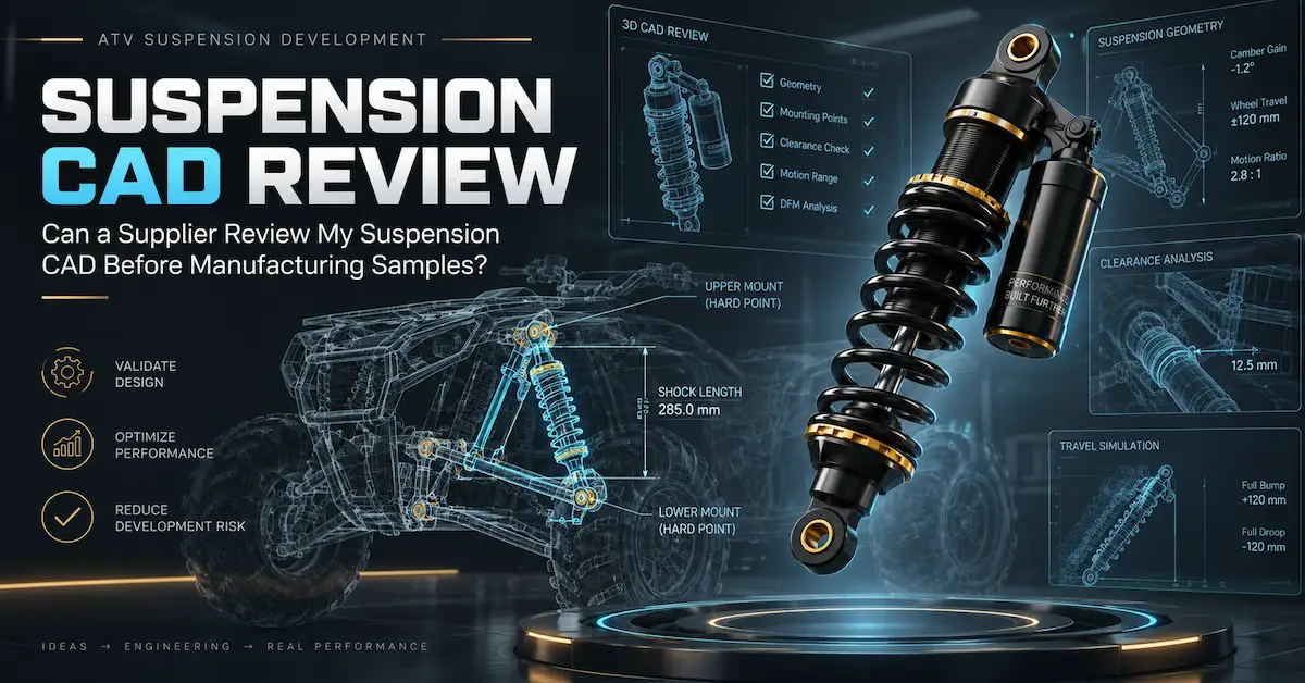
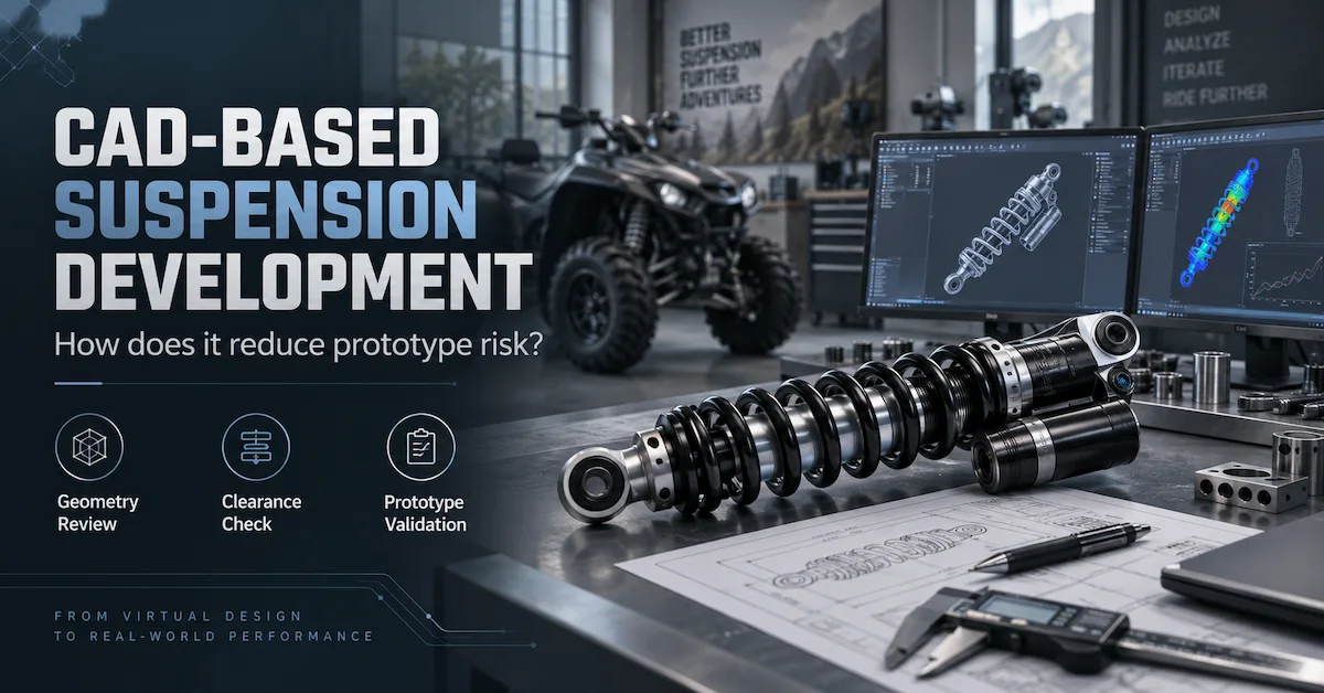
CAD-based suspension development reduces prototype risk by moving fitment, geometry, movement, and packaging questions into the digital review stage before metal parts are manufactured. Engineers can compare shock position, mounting points, wheel and tire envelopes, control-arm movement, reservoir location, and surrounding components through multiple suspension positions, then identify obvious interference or dimensional conflicts before a prototype is ordered. BEDO’s CAD-based suspension development process reflects this approach by combining digital vehicle information with component development rather than treating CAD as a simple presentation file.
The benefit is not that CAD removes the need for prototypes. It helps ensure the prototype is built to answer meaningful engineering questions instead of discovering avoidable dimensional mistakes. A strong workflow is therefore Vehicle Data → CAD Review → Drawing Release → Prototype → Vehicle Validation → Revision → Pilot Production, rather than prototype first and geometry review later.
Which Buyers Benefit Most from CAD-Based Suspension Development?
CAD review is especially valuable for ATV manufacturers developing a new platform, aftermarket brands creating vehicle-specific upgrades, custom vehicle builders changing suspension geometry, and OEM buyers commissioning products with non-standard dimensions. These projects often include several interacting components, so a change to one shock dimension can affect tire clearance, control-arm movement, mounting angle, available travel, or reservoir packaging.
A straightforward replacement project with an unchanged, fully verified application may not require a complete vehicle CAD model. In that case, an existing sample, controlled drawing, measurements, and verified fitment data may be sufficient for initial engineering. BEDO’s custom suspension development files guide explains why buyers should send the smallest complete data package necessary for the actual engineering problem rather than automatically transferring an entire vehicle model.
What Prototype Risks Can CAD Identify Before Parts Are Made?
The main advantage of CAD is that several forms of risk can be reviewed while changes are still digital. Some problems are difficult to see from an isolated shock drawing because they only appear when the component is installed in the vehicle.
| Prototype risk | What CAD can help review | What still needs physical validation |
|---|---|---|
| Wrong mounting location | Upper/lower hard-point relationship | Real bracket fit and assembly |
| Shock-body interference | Body/spring envelope against chassis | Production tolerances and real installation |
| Tire contact | Tire envelope through bump/steering | Actual tire deflection and vehicle test |
| Insufficient bump clearance | Shock and suspension positions at compression | Physical bump-stop behavior |
| Excessive droop | Shock extension and component movement | Joint, hose and real-vehicle limits |
| Reservoir interference | Piggyback or remote reservoir packaging | Hose routing and service access |
| Incorrect shock angle | Installation geometry through movement | Final vehicle behavior |
| CAD/drawing mismatch | Digital revision comparison | Production document control |
| Wrong spring/damping | CAD can show packaging only | Spring and damping testing required |
| Leakage/durability | Cannot be proven by geometry | Prototype and durability testing required |
This distinction matters because CAD is strongest at detecting geometric and packaging risk. It cannot prove hydraulic performance, seal durability, damping consistency, spring fatigue, or real-world ride quality.
Start With Vehicle Hard Points, Not a Finished Shock Model
A supplier cannot evaluate suspension movement accurately if it receives only a beautiful 3D model of the shock. The most important vehicle inputs are often the hard points that define where suspension parts pivot and where the damper attaches.
For an ATV project, relevant data may include:
- upper shock mount;
- lower shock mount;
- control-arm pivots;
- wheel center;
- tire envelope;
- steering interface;
- bump-stop position;
- chassis boundaries;
- reservoir mounting area;
- ride-height position;
- full-bump position;
- full-droop position.
For long-travel development, BEDO’s long-travel shock absorber guide shows why wheel movement and shock movement must be evaluated separately. A target such as “more wheel travel” should not be translated directly into a longer shock without reviewing the actual suspension geometry.
Use CAD to Check Full Bump, Ride Height, and Full Droop
A static CAD screenshot at ride height provides only one part of the story. The suspension should be reviewed through its relevant movement range.
At full bump, engineering should examine tire-to-body clearance, spring and shock-body clearance, bump-stop engagement, reservoir location, and whether the damper reaches its mechanical compression limit before another intended stop.
At ride height, check the installed shock angle, spring position, available compression and rebound travel, surrounding packaging, and any required adjuster access.
At full droop, review shock extension, spring seating, joint movement, hose or cable routing, and whether the shock or another suspension component becomes the limiting element.
Where steering movement interacts with the suspension, review combined positions instead of evaluating steering and vertical movement independently.
CAD Can Show Why Catalog Dimensions Are Not Enough
BEDO’s AU_HSA_01 and AU_HSA_03 provide a useful example. Both published products list a 130 mm effective stroke and 10 mm upper and lower mounting-hole diameters, yet their overall dimensions and mounting widths differ.
The same stroke does not mean the same installed geometry. One shock may occupy a different space, sit at another angle, or require another bracket arrangement. CAD allows the supplier to move beyond a catalog-table comparison and evaluate whether the actual component envelope fits the intended vehicle.
The product pages use the term total length. A custom-development project should still confirm the measurement reference on the controlled drawing rather than automatically treating that value as an eye-to-eye dimension.
Keep 2D Drawings and CAD Models Working Together
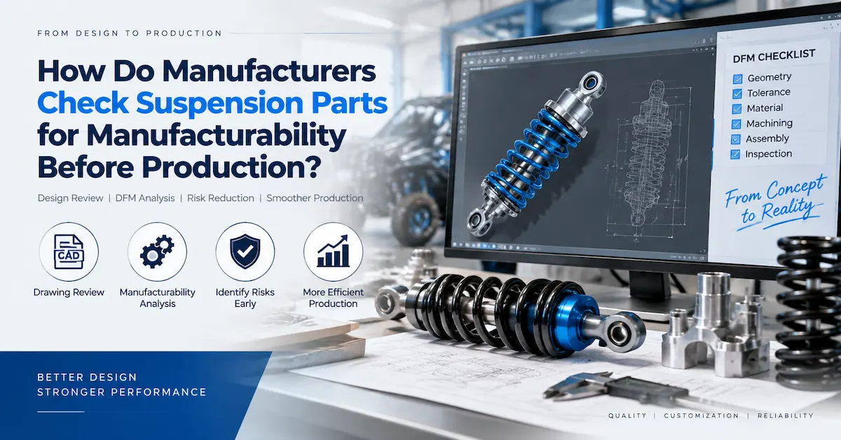
The CAD model helps answer where the product fits and how it moves, while the controlled technical drawing defines what the manufacturer must build and inspect. BEDO’s 2D drawings and 3D CAD guide explains why the two formats often complement one another.
A drawing may specify:
- extended and compressed lengths;
- stroke;
- mounting-hole diameters;
- mounting widths;
- body and spring envelopes;
- tolerances;
- materials or finish requirements;
- product code;
- revision.
The CAD assembly can then place that controlled component into the vehicle environment.
The most important issue is revision alignment. If the CAD model contains one mounting width and the 2D drawing contains another, the project should stop until engineering identifies which value is correct and releases an updated package.
Use Revision Control to Prevent the Wrong Prototype from Being Built
A surprising amount of prototype risk comes from document management rather than suspension theory. A buyer may send one CAD revision, later email a revised drawing, then approve a spring change through a message without updating the project package.
The manufacturer may then manufacture a perfectly accurate prototype to the wrong revision.
A simple file register can reduce that risk:
| Document | Revision | Status | Use |
|---|---|---|---|
| Vehicle suspension CAD | Rev B | Current | Geometry review |
| Shock drawing | Rev C | Current | Prototype manufacturing |
| Load data | Rev A | Current | Spring development |
| Spring specification | Rev B | Pending validation | Prototype |
| Damping specification | Prototype 02 | Pending test | Vehicle evaluation |
| Prototype acceptance plan | Rev A | Released | Test criteria |
Every prototype should be traceable back to the specific files used to produce it.
CAD Review Should Include the Tire and Wheel Package
Tire clearance is one of the clearest examples of risk that digital vehicle data can expose before prototype manufacture. A larger tire can approach the spring, shock body, control arms, fender, or other components differently as the suspension compresses or the steering turns.
If the project involves larger tires or aftermarket accessories, include those configurations in the model rather than reviewing the suspension against the standard vehicle. BEDO’s ATV shocks for larger tires and accessories guide explains why modified tire packages, accessory loads, and clearance need separate consideration.
For buyers, this prevents a common mistake: approving a shock against the original ATV CAD and later discovering that the actual commercial product is sold mainly to customers using larger tires.
Reservoir Shocks Benefit from Digital Packaging Review
Piggyback and remote-reservoir products introduce additional packaging constraints. A piggyback reservoir occupies space directly beside the shock body. A remote reservoir requires a mounting location plus hose routing.
CAD can help evaluate:
- reservoir orientation;
- hose length requirements;
- potential tire contact;
- chassis abrasion points;
- proximity to hot components;
- mounting-bracket space;
- adjuster accessibility;
- full-bump and full-droop hose movement.
BEDO’s remote-reservoir ATV shock guide explains why reservoir architecture should follow application and packaging requirements rather than be added only as a premium visual feature.
CAD Helps Reduce Long-Travel Prototype Risk
Long-travel development is one of the strongest applications for CAD-based suspension development because changing shock movement can affect almost every surrounding suspension component.
The engineering team may need to evaluate:
Target Wheel Travel → Hard Points → Shock Motion → Extended/Compressed Dimensions → Joint Angles → Tire Clearance → Steering Clearance → Spring → Damping
A longer physical shock does not automatically produce a valid long-travel suspension. CAD can reveal whether the new movement causes the tire, control arm, axle, steering system, hose, or another component to reach a limit before the shock uses its intended travel.
This does not make the shock manufacturer responsible for the complete vehicle system unless that broader engineering scope has been agreed. It simply allows vehicle and shock engineers to identify the interfaces that must be validated before the prototype is built.
CAD Does Not Select the Correct Spring by Itself
A CAD model can show the spring dimensions and available compression space, but it cannot determine the correct spring rate without load and application data.
The supplier may still need:
- vehicle weight;
- front/rear distribution;
- rider weight;
- cargo;
- accessories;
- target ride height;
- sag requirement;
- suspension motion relationship;
- terrain;
- intended vehicle behavior.
The same principle applies to damping. A digital model may define the damper geometry but does not prove the correct compression or rebound force.
BEDO’s custom shock absorber development guide connects geometry with load, spring, damping, and performance targets rather than treating CAD as a complete suspension specification.
Virtual Interference Checks Do Not Replace a Physical Prototype
CAD should reduce prototype risk, not eliminate prototypes from the development process.
A physical sample is still needed to evaluate factors such as:
- actual manufacturing variation;
- bushing fit;
- assembly alignment;
- seal behavior;
- leakage;
- spring characteristics;
- damping performance;
- adjuster function;
- noise;
- real vehicle response;
- long-term durability.
BEDO’s suspension sample development process positions the prototype as an engineering verification stage after technical review.
The difference is that a better digital stage allows the prototype to answer performance and manufacturing questions instead of wasting the first sample on an obvious clearance problem.
Define Prototype Acceptance Before the Sample Is Manufactured
Do not wait until the prototype arrives to decide whether it passed.
For a CAD-driven project, create an acceptance plan that connects digital predictions to physical checks.
| Prototype check | CAD-stage expectation | Physical validation |
|---|---|---|
| Mounting position | Digital interface matches | Bolt/sleeve fit confirmed |
| Body clearance | Digital minimum clearance reviewed | Actual installed clearance checked |
| Full bump | Model shows required movement | Vehicle is physically cycled/tested |
| Full droop | Geometry remains within planned range | Actual component movement checked |
| Tire clearance | Digital tire envelope clears | Real tire/wheel setup confirmed |
| Reservoir | Location and routing reviewed | Bracket/hose installation checked |
| Spring | Envelope fits geometry | Sag/load behavior validated |
| Damping | Packaging defined | Bench and vehicle behavior tested |
This approach turns CAD predictions into explicit prototype test items.
How Does CAD Reduce Revision Cycles?
Without early geometry review, the first sample may reveal a mounting-width problem. The second may correct the width but discover reservoir interference. The third may correct packaging but need another body length.
CAD cannot guarantee that one prototype will be enough, but it can move many of these discoverable geometric conflicts into the same digital review cycle.
That matters commercially because each additional physical revision can involve:
- engineering time;
- new parts;
- machining;
- assembly;
- international shipping;
- vehicle installation;
- testing;
- buyer review;
- another drawing update.
The value of CAD is therefore not merely “designing in 3D.” It is resolving low-cost digital questions before they become higher-cost physical questions.
CAD Review Also Improves Supplier Quotation Quality
A manufacturer quoting from a single photograph may need to make assumptions about geometry and complexity. Once relevant CAD and drawings are available, the supplier can better identify whether the project uses an existing platform, requires dimensional modification, or needs deeper engineering work.
A more complete package can clarify:
- new vs existing mounting components;
- body packaging;
- reservoir requirements;
- custom spring needs;
- tooling or fixture needs;
- prototype scope;
- inspection requirements.
This does not guarantee a lower quotation. It produces a quotation based on a more clearly defined scope, which is more useful for comparing suppliers.
Use CAD to Support Manufacturing Feasibility, Not Only Vehicle Fitment
After vehicle packaging is reviewed, the component still needs to be manufacturable. Ask the supplier to review whether proposed dimensions, material thicknesses, threaded features, mounting structures, and assembly access are practical for the intended production method.
BEDO’s ATV shock absorber production guide connects engineering review with subsequent material selection, component production, assembly, testing, and inspection.
For a custom program, an engineering change that simplifies manufacturing should not be implemented silently. It should flow back into the approved CAD, drawing, and prototype revision.
Move from CAD to Prototype Through a Controlled Engineering Release
A practical CAD-based suspension development workflow can use the following release points:
Stage 1 – Vehicle Data Review
Confirm hard points, loads, tire package, surrounding components, and performance target.
Stage 2 – Digital Suspension Review
Evaluate shock envelope, travel, mounting, geometry, interference, reservoir packaging, and component movement.
Stage 3 – Drawing Release for Prototype
Freeze dimensions and identify unresolved performance items separately.
Stage 4 – Prototype Manufacturing
Produce the sample to the released drawing and documented spring/damping configuration.
Stage 5 – Physical Validation
Confirm fitment, full movement, spring behavior, damping, leakage, and representative vehicle performance.
Stage 6 – Engineering Revision
Update the model and drawing when testing produces an approved change.
Stage 7 – Pilot Production
Confirm the manufacturing process can reproduce the approved design.
This separates digital approval from dynamic performance approval and production approval.
When Is a Pilot Batch Worth Adding?
For a standard product using established manufacturing processes, the path from prototype to production may be relatively direct. For a new geometry, reservoir layout, spring configuration, or private-label performance product, a small pilot batch can add another layer of risk control.
BEDO supports low-volume shock absorber development, allowing buyers to validate custom suspension projects before committing to larger orders.
The pilot batch can verify:
- critical dimensions;
- mounting hardware;
- spring version;
- damping configuration;
- reservoir/hose assembly;
- finish;
- labeling;
- packaging;
- batch traceability.
Exact prototype quantities, MOQ, available capacity, and lead time should still be confirmed for the particular project.
What Should You Send BEDO for a CAD-Based Project?
For an efficient review, prepare the data needed to describe both the vehicle and the intended suspension.
A useful starting package includes:
- ATV make/model/year or internal platform code;
- front/rear position;
- vehicle hard points;
- relevant chassis CAD;
- control-arm geometry where required;
- wheel and tire envelope;
- current shock drawing or model;
- existing sample information;
- vehicle and rider loads;
- cargo/accessory loads;
- target wheel/shock movement;
- current suspension problem;
- required performance change;
- prototype quantity;
- expected production volume.
BEDO’s custom suspension development files guide provides a related framework for organizing drawings, CAD, samples, load information, and validation requirements.
Frequently Asked Questions
1. Can CAD eliminate the need for suspension prototypes?
No. CAD can reduce geometric and packaging uncertainty, but physical prototypes remain important for manufacturing variation, spring behavior, damping, sealing, vehicle performance, and durability validation.
2. Do I need full vehicle CAD for a custom shock project?
Not necessarily. Send the geometry required to evaluate the relevant suspension interfaces. For a simple replacement, a drawing and sample may be sufficient; geometry-sensitive projects may require more vehicle data.
3. Can CAD determine the correct shock stroke?
CAD can help establish the damper movement required by the suspension geometry, but the final specification should also consider vehicle movement limits, bump/droop conditions, and validation requirements.
4. Can CAD determine spring rate?
Not by geometry alone. Spring selection also requires vehicle load, motion relationship, target ride height, sag, and application data.
5. What clearance problems can CAD help identify?
Typical checks include tire-to-spring clearance, shock-to-frame interference, control-arm contact, reservoir packaging, hose routing, body clearance, and adjuster access through the intended suspension movement.
6. Is 2D drawing data still necessary when CAD is available?
It depends on the agreed engineering workflow. CAD provides geometry, while controlled drawings commonly communicate critical dimensions, tolerances, notes, and manufacturing/inspection requirements. See BEDO’s drawing and CAD guide.
7. Can CAD reduce custom suspension development cost?
It can help reduce avoidable physical rework by identifying digital fitment and geometry issues earlier. Actual project cost still depends on engineering scope, prototypes, testing, tooling, components, and production requirements.
8.Does CAD prove that damping will perform correctly?
No. Damping is a hydraulic performance characteristic and requires appropriate bench and/or vehicle validation. CAD mainly helps define geometry and packaging.
9. Should the CAD model be updated after prototype testing?
Yes when an approved test result leads to a design change. The released model, drawing, prototype configuration, and production specification should remain aligned.
10. What should I include in the first CAD package sent to BEDO?
Provide the target vehicle, suspension position, relevant geometry, current shock data, wheel/tire information, loads, target changes, application conditions, and expected quantities. BEDO can then identify whether more CAD, measurements, or sample information is needed.
Conclusion
CAD-based suspension development reduces prototype risk by resolving vehicle geometry, mounting, clearance, travel, and packaging questions before physical manufacturing begins. Its strongest value is not eliminating prototypes but improving what each prototype is designed to validate: instead of discovering an avoidable interference problem, the physical sample can focus on spring behavior, damping, assembly quality, sealing, and real vehicle performance. The most effective workflow links controlled CAD, 2D drawings, vehicle loads, prototype acceptance criteria, and revision management from engineering through pilot production. BEDO supports drawing-, CAD-, and sample-based suspension development for custom ATV and off-road projects. To review your project, contact BEDO with your relevant CAD, hard points, drawings, load data, tire information, current suspension problem, and expected order volume so the digital review scope and prototype plan can be defined before manufacturing starts.