
How should an OEM buyer select an ATV rear shock absorber?
Direct answer: select an ATV rear shock absorber by matching the complete rear suspension requirement: extended and compressed length, effective stroke, upper and lower mounting interfaces, axle load, spring rate, preload, compression and rebound damping, installation angle, bump and droop limits, terrain, and duty cycle. A part should not be approved because its overall length or product photo looks similar.
The buyer should first prove fitment, then prove load support and motion control, and finally prove repeatable production. The supplier RFQ should include a measured sample or drawing, vehicle and rider loads, accessories, current ride problem, target result, sample quantity, test plan, and commercial forecast.
This article is for ATV manufacturers, powersports brands, aftermarket distributors, private-label buyers, farm and utility vehicle developers, and engineering teams preparing an ATV rear shock absorber RFQ. Its unique search task is technical selection before quotation. It does not duplicate a supplier-ranking article, a farm-duty guide, or a troubleshooting page.
Fitment begins with five measurements, not one
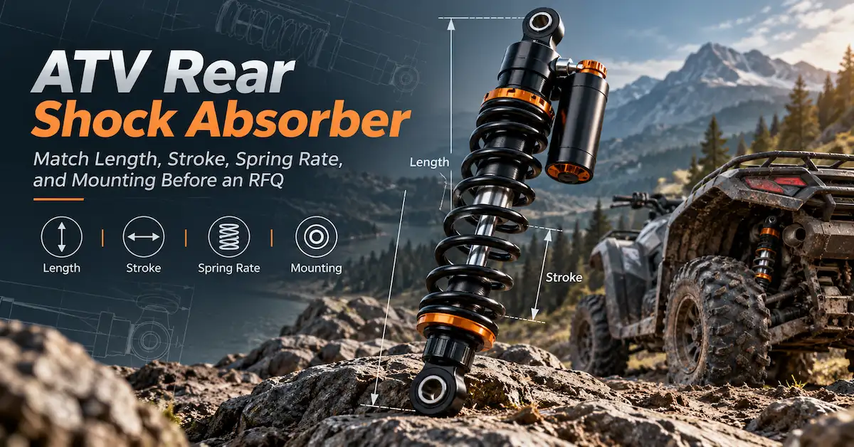
Extended length
Extended length affects maximum droop and whether the shock becomes the travel limiter. Measure between the same mounting datums used by the supplier. Do not mix center-to-center, shoulder-to-shoulder, or overall body measurements. At full droop, check the drive shaft, brake line, ball joint, chain or belt, control arm, spring seat, and tire. The shock should only limit droop if the vehicle design explicitly intends it to do so.
Compressed length
Compressed length protects the shock at full bump. Confirm that the vehicle's bump stop engages before the shock reaches a damaging mechanical limit, unless the shock assembly has been designed and validated to carry that stop load. Check body, spring, reservoir, tire, fender, exhaust, and frame clearance. A replacement can match extended length and still be too long when compressed.
Effective stroke
Shock stroke is not automatically wheel travel. Installation angle and linkage motion ratio determine how wheel movement translates into shock movement. Record both. An ATV rear shock absorber with greater stroke is not automatically better if the chassis cannot use the travel safely or the spring reaches coil bind.
Mounting hole and installation width
Upper and lower interfaces may use different holes, sleeves, bushings, or widths. Measure hole diameter, sleeve inner and outer diameter, bracket width, bushing face width, fastener size, and orientation. Check side clearance and articulation through travel. Do not force a narrow or wide eye into the bracket with an improvised spacer stack.
Body, spring, and adjustment clearance
Measure body diameter, spring outside diameter, reservoir position, hose path, preload adjuster, and any damping knob. Check access after the bodywork is installed. A feature that cannot be reached on the vehicle adds cost without providing usable adjustment.
| Fitment field | Buyer record | Failure if omitted |
|---|---|---|
| Extended length | Datum, value, tolerance and full-droop vehicle condition. | Joint over-angle, line tension, spring unseating or shock top-out. |
| Compressed length | Datum, value, bump-stop relationship and clearance. | Shock bottoms internally or contacts chassis/tire. |
| Stroke | Usable shock movement and corresponding wheel travel. | Lost travel, coil bind, or incorrect performance assumption. |
| Mounting | Holes, sleeves, widths, bushing and fastener. | Loose, offset, preloaded or impossible installation. |
| Envelope | Body, spring, reservoir, adjuster and service access. | Interference, damaged hose, blocked adjuster or assembly delay. |
Match the spring to actual rear-axle loads
The rear spring supports the ATV, rider, passenger where applicable, rear rack, cargo, battery, tools, sprayer, tow load, and accessories. Record the rear axle load with the vehicle unloaded, normally loaded, and at the maximum intended routine condition. A single vehicle curb-weight number does not show how much mass the rear spring carries.
Spring rate describes the force required for a unit of deflection, but the published value must be read with its unit, measurement convention, tolerance, installed length, and preload. The same nominal rate can produce different ride heights when free length, preload, motion ratio, and vehicle load differ.
Use preload for setup, not to hide the wrong spring
Preload changes initial spring compression and can adjust sag or ride height within a useful range. It does not change the basic spring rate. Excessive preload on a spring that is too soft may restore static height while leaving poor reserve travel or an unsuitable response. A spring that is too stiff for the empty condition may preserve height but reduce comfort and tire contact.
Define sag and reserve travel
Choose consistent chassis measurement points. Record the vehicle with suspension topped out, at curb condition, with rider, and with normal cargo. The useful target depends on the ATV geometry and use, so avoid importing a generic percentage without engineering approval. The important question is whether enough compression and extension travel remain for the intended terrain.
Separate support from damping
A spring holds the load; the shock controls motion. If the rear sits too low, investigate spring support, preload, load location, and geometry. If the vehicle continues bouncing after a bump, investigate damping, tire, bushing, and shock condition. Replacing a shock to solve spring sag can create an expensive part that does not address the cause.
Read compression and rebound data correctly
Compression damping resists the shock as it shortens. Rebound damping resists extension after the spring releases energy. Both depend on shaft velocity, temperature, stroke position, valve design, oil condition, gas condition, and adjustment setting. A single maximum force is a reference point, not a complete force-velocity curve.
When comparing an ATV rear shock absorber, request the test direction, velocity, units, temperature or conditioning, setting, tolerance, and sample revision. BEDO's public ATV/UTV pages state an inspection speed of 0.1 m/s with their listed maximum rebound and compression fields. That common published condition makes the figures easier to read side by side, but the buyer should still request the underlying current data before engineering release.
Too little compression control
Possible symptoms include rapid travel use, bottoming, excessive chassis movement, or poor support during repeated impacts. Confirm the spring and bump-stop condition before assigning the symptom to damping.
Too much compression control
Possible symptoms include a sharp ride, deflection from obstacles, reduced tire compliance, or high loads at mounts. Tire pressure, spring rate, friction, and speed can create similar complaints.
Too little rebound control
The rear may continue oscillating, extend quickly, or feel loose after a bump. This can become more visible after a stiffer spring is installed without a matching damping review.
Too much rebound control
The suspension may recover too slowly over a series of bumps and work progressively lower in its travel. Test on a repeatable section and record load, speed, tire pressure, and temperature before changing the specification.
Compare four public BEDO ATV/UTV rear shock references
The following table transcribes current public product-page fields for four BEDO rear shock references. It is a selection aid, not an application chart. None should be described as a direct-fit part for a specific ATV until mounting, geometry, load, and vehicle validation are complete.
| Reference | Length / stroke | Spring / damping at listed inspection condition | Mounting |
|---|---|---|---|
| AU_HSA_01 | 465 mm total; 130 mm effective stroke; 38 mm cylinder OD. | 75 LBS; 2000 N rebound; 650 N compression; fixed damping. | 10 mm upper/lower holes; 32 mm upper/lower widths. |
| AU_HSA_02 | 395 mm total; 80 mm effective stroke; 38 mm cylinder OD. | 250 LBS; 3000 N rebound; 550 N compression; fixed damping. | 12 mm upper/lower holes; 40 mm upper and 32 mm lower widths. |
| AU_HSA_03 | 445 mm total; 130 mm effective stroke; 42 mm cylinder OD. | 135 LBS; 2700 N rebound; 350 N compression; fixed damping. | 10 mm upper/lower holes; 30 mm upper and 35 mm lower widths. |
| AU_HSA_04 | 345 mm total; 80 mm effective stroke; 42 mm cylinder OD. | 225 LBS; 3000 N rebound; 350 N compression; fixed damping. | 10 mm upper/lower holes; 32 mm upper and 30 mm lower widths. |
All four pages list a rear position, internal gas chamber, oil-gas separation, aluminum alloy and steel pipe, and a 0.1 m/s inspection speed. The differences in length, stroke, spring, force, body diameter, and mounting show why "ATV rear shock" is not a complete specification. Even two references with 130 mm stroke use different total length, body diameter, spring rate, damping values, and mounting widths.
Fixed damping or adjustable damping?
The four public ATV/UTV references above are listed as fixed damping. A validated fixed setting can suit a controlled vehicle and load range, reduce user setup errors, simplify instructions, and support consistent replacement. It should still be proven on the target ATV.
Adjustment can be useful when rider, cargo, terrain, or performance goals change enough to require different control. The buyer should define which direction is adjustable, how many settings are usable, the baseline, the force change across the range, the click or position repeatability, access on the installed vehicle, and the customer instruction.
An adjustment count is not a quality score. If several positions produce little measurable change, or the end settings make the ATV difficult to control, the feature adds complexity without solving a buyer problem. Decide from vehicle conditions and evidence.
Materials, sealing, finish, and off-road exposure
The referenced BEDO pages list aluminum alloy and steel pipe. They also use corrosion-resistant, waterproof, and rust-proof language. For an OEM or private-label order, convert those descriptions into controlled requirements: material specification, surface process, protected areas, coating appearance, rod-surface requirement, seal configuration, dust protection, and acceptance method.
Describe mud, water, sand, dust, salt, fertilizer, pressure washing, outdoor storage, and temperature. Ask how the shock is cleaned before assembly, how leakage is checked, and what evidence is available for the specified environment. Do not publish a corrosion-hour value, ingress rating, cycle life, or named material grade unless it appears in an approved product record.
Inspect the spring coating near seats and contact points, the rod for damage, the eye and bushing alignment, reservoir or body clearance, and the label after the durability route. A good-looking finish at shipment does not prove durability; the test condition and acceptance criteria must be stated.
Prototype the shock on the final ATV configuration
Freeze the test vehicle
Record ATV revision, tire, pressure, rider, fuel or battery state, accessories, rack load, alignment, spring preload, and shock setting. Do not change several variables between runs. If the ATV is still under development, identify the parts that may alter mass or geometry.
Inspect before riding
Verify holes, widths, fasteners, torque, orientation, line and tire clearance, spring seating, preload, and static ride height. Move the suspension safely through expected bump and droop conditions before dynamic testing. Stop if a hose, spring, shock body, or mounting eye contacts another part.
Test several load states
Evaluate curb, rider, normal cargo, and maximum intended routine load. Record sag and ride height at consistent points. A setting that feels controlled with cargo may be harsh when empty; a comfortable empty setup may bottom when loaded.
Use a repeatable route
Include representative small bumps, larger impacts, repeated bumps, braking, acceleration, turns, climbs, and descents as appropriate. Record speed range and observations. The objective is not to create the harshest possible test but to reproduce the market use that the ATV rear shock absorber must support.
Inspect after the test
Check leakage, rod, spring seats, coating, bushings, mounting torque, noise, contact marks, and ride-height change. Link photos and data to sample revision. If the sample changes, issue a new revision rather than editing the old record.
Validate rear shocks as an installed pair
When an ATV uses two rear shocks, do not approve each unit only as an isolated bench sample. Confirm that left and right parts have the same released identity, spring specification, preload reference, mounting hardware, and damping revision unless the vehicle design intentionally requires different sides. Measure ride height at consistent chassis points on level ground and investigate side-to-side differences before changing preload.
Installation effects can create an apparent shock problem. Check bracket alignment, sleeve width, bushing compression, fastener torque, tire pressure, wheel or axle condition, and unequal accessory mass. Disconnect or unload components only under an approved workshop procedure. The objective is to separate a vehicle assembly issue from variation in the ATV rear shock absorber.
After the first controlled run, compare leakage, temperature, spring seating, rod marks, bushing movement, and witness marks on both sides. If one side behaves differently, preserve the complete configuration and record the unit or batch identity before disassembly. A useful supplier report states the load state, route, duration, symptom, side, measurement method, photographs, and whether swapping parts moved the symptom. This evidence gives engineering a reproducible problem instead of a general complaint such as "the rear feels uneven."
If a unit must be returned for analysis, agree on preservation and shipping before draining, cleaning, opening, or adjusting it. Photograph the installed condition, labels, preload position, mounts, rod, spring seats, and any residue. Record the vehicle, mileage or test hours, event sequence, operating load, and storage condition. Ask the supplier to issue an analysis plan that separates external inspection, dimensional checks, functional or force testing, controlled disassembly, likely cause, containment, and corrective action. The report should identify which observations are facts and which are hypotheses. It should also state whether other units, batches, or revisions may be affected and what evidence is required before the vehicle returns to service.
Move from prototype to repeat production
| Control | Prototype question | Production requirement |
|---|---|---|
| Dimensions | Does the shock fit and clear at bump/droop? | Drawing, tolerances, gauges or measurement plan. |
| Spring | Does it support the approved load range? | Rate/load points, dimensions, preload, finish and identification. |
| Damping | Does the vehicle meet the motion-control target? | Test condition, target or limits, sampling and traceability. |
| Sealing | Is there leakage or abnormal friction after validation? | Assembly controls, functional check and nonconformance response. |
| Mounting | Are bushing, sleeve and hardware correct? | Incoming/assembly checks and pack verification. |
| Identity | Can the approved sample be distinguished? | Part number, revision, batch, label and change notification. |
A pilot batch is useful because one handmade or closely monitored sample may not reveal normal process variation. Compare several units for dimensions, spring fields, damping evidence, leakage, appearance, labels, and packaging. Confirm how a failed unit is contained and how the supplier investigates the cause.
Prepare an ATV rear shock absorber RFQ
Send the vehicle brand, model, year, project code, rear suspension layout, target market, rider and cargo states, accessories, terrain, speed, daily duty, environment, current problem, and desired result. Add a dimensioned drawing or sample with extended length, compressed length, stroke, upper/lower holes, widths, sleeves, spring dimensions, installation angle, body envelope, and motion ratio where available.
State whether the buyer wants a direct replacement, a revised spring or damping setup, an adjustable product, or a new vehicle-specific development. Include sample quantity, pilot quantity, annual forecast, color, logo, labels, hardware, instructions, carton, delivery location, and target timing.
Ask BEDO to return a proposed product or development path, confirmed dimensions, assumptions, missing inputs, spring and damping basis, sample configuration, test evidence, MOQ by stage, stage lead time, packaging, unit-price basis, and change-control terms. The public OEM ATV shock page requests model and year details for OEM references, pricing tiers, customization, and lead-time discussion.
ATV rear shock absorber FAQ
Can I select an ATV rear shock by eye-to-eye length?
No. Confirm compressed length, stroke, mounting holes, widths, sleeves, spring/body clearance, angle, motion ratio, bump stop, droop limit, axle load, spring, and damping.
Is more stroke always better?
No. The chassis, linkage, joints, tire, spring, and bump-stop strategy must safely use it. Excess stroke can be unusable or create interference.
What does spring rate tell me?
It indicates load per unit deflection under a stated convention. It does not by itself determine ride height or suitability; free length, installed length, preload, motion ratio, and rear load also matter.
Why are rebound and compression values different?
They control different directions of motion. Valve design and the vehicle target determine the relationship. Compare values only under the same test conditions.
Are the BEDO AU_HSA references direct-fit for every ATV?
No. They are public configurations with published fields. Model-specific fitment requires drawing or sample review and vehicle validation.
When is fixed damping appropriate?
A validated fixed setup is practical when vehicle, load, terrain, and user expectations are controlled. It can reduce setup mistakes and support repeatable replacement.
What should be checked after installation?
Check torque, orientation, clearance, spring seating, ride height, sag, leakage, noise, bottoming, rebound, contact marks, and bushing condition across intended load states.
Does BEDO publish a universal MOQ?
No universal product MOQ is shown on the reviewed pages. The company states support for small-batch orders, so request prototype, pilot, and production minimums for the exact configuration.
What evidence is required before this page is published?
Add a named engineer and reviewer, confirm current product values and the AU_HSA_05 anomaly, provide approved production/test evidence, and insert project-specific MOQ, lead time, packaging, and a case only when documented.
Conclusion
An ATV rear shock absorber is an application-specific assembly, not a length-only replacement. Reliable selection starts with fitment and mechanical limits, then connects rear-axle loads to spring support and damping control. A controlled prototype, repeatable vehicle test, pilot batch, inspection plan, and clear commercial terms turn the selection into a producible part.
BEDO Auto publishes several useful ATV/UTV rear references, including AU_HSA_03 with 445 mm total length, 130 mm effective stroke, 135 LBS listed spring rate, fixed damping, and defined mounting dimensions. Those facts create a concrete RFQ starting point. The buyer should send the final ATV data so BEDO can confirm the correct reference or develop a revised configuration.