
What Does “Suspension Parts From Drawings” Mean?
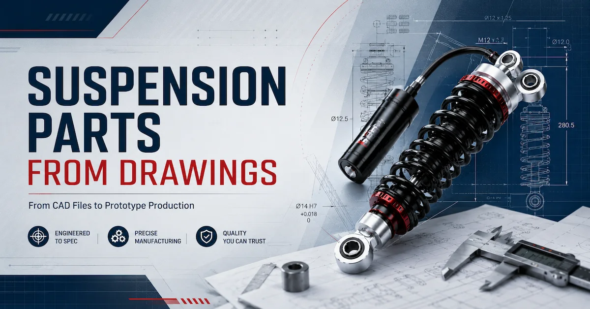
Suspension parts from drawings refers to developing or manufacturing suspension components according to customer-provided technical drawings, CAD models, dimensional sketches, reference samples, or other engineering specifications.
For OEM buyers, this approach is useful when an existing catalog component cannot meet the required vehicle geometry, mounting interface, packaging space, or product configuration.
Instead of choosing the closest available part and adapting the vehicle around it, the project starts with the buyer's engineering requirements.
Typical inputs may include:
- 2D technical drawings
- 3D CAD models
- Existing suspension samples
- Vehicle CAD data
- Mounting dimensions
- Material requirements
- Surface-finish requirements
- Target tolerances
- Prototype quantities
- Future production plans
The drawing becomes the technical reference connecting the buyer's engineering team with prototype, manufacturing, quality, and purchasing teams.
However, a drawing alone does not prove that a suspension component will perform correctly on a vehicle. Fitment, assembly, load behavior, damping, durability, and production consistency may still require prototype and physical validation.
That is why drawing-based manufacturing is most useful when it is connected to an engineering process rather than treated as simple copy production.
Which Suspension Parts Can Be Developed From Drawings?
The exact scope depends on the supplier's manufacturing capabilities and the project requirements.
In suspension projects, drawings may be used to define components such as:
- Shock absorber assemblies
- Shock mounting eyes
- Fork or clevis mounts
- Bushings and sleeves
- Spring seats
- Adjustment collars
- Mounting brackets
- Reservoir mounting components
- Suspension-related machined components
- Custom interfaces between the shock and vehicle
For shock absorber projects, the drawing may also define the overall assembly geometry rather than individual components alone.
Important parameters can include:
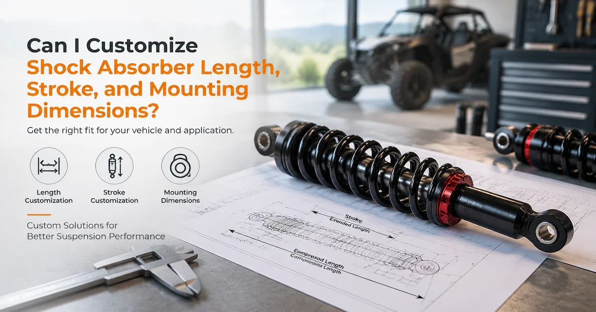
| Drawing Item | Typical Information |
|---|---|
| Extended length | Maximum eye-to-eye or mounting reference |
| Compressed length | Minimum allowable overall length |
| Stroke | Available shock movement |
| Upper mount | Eye, fork, clevis or other interface |
| Lower mount | Eye, fork, clevis or other interface |
| Mounting hole | Diameter and positional requirements |
| Bushing width | Interface with vehicle bracket |
| Shock body | Diameter and packaging envelope |
| Spring area | OD, free-space and seat location |
| Reservoir | Position, orientation and clearance |
| Surface finish | Plating, coating or other requirement |
| Tolerances | Critical dimensional limits |
Buyers who are still defining the full shock absorber can first review the Bedo Auto shock absorber drawing service to understand how vehicle requirements and reference components can be converted into technical documentation.
Why Do OEM Buyers Source Suspension Parts From Drawings?
Drawing-based sourcing is particularly valuable when a project requires repeatability and engineering control.
Custom Vehicle Geometry
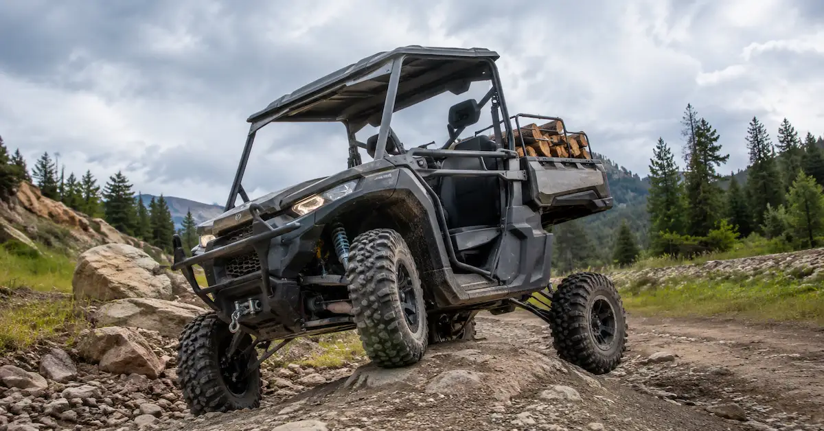
ATV, UTV, motorcycles, electric vehicles, utility vehicles, and specialty platforms can have different:
- Suspension layouts
- Mounting dimensions
- Available installation space
- Vehicle weight
- Wheel travel
- Load conditions
An existing component may be close in size but still fail to fit correctly.
Producing suspension parts from approved drawings provides a clearer basis for dimensional control.
Replacement of Non-Standard Components
Some buyers need to reproduce or redesign a suspension component when:
- The original supplier is unavailable
- The original drawing is incomplete
- The existing component has been discontinued
- A new vehicle version uses different geometry
- A reference component needs modification
A physical sample can support this process, but buyers should avoid assuming that simply copying an old sample will produce the correct result for a new application.
New OEM Suspension Projects
For a new vehicle platform, drawings can become part of a larger development process:
Vehicle Requirement → CAD Design → Drawing Review → Prototype → Testing → Revision → Production
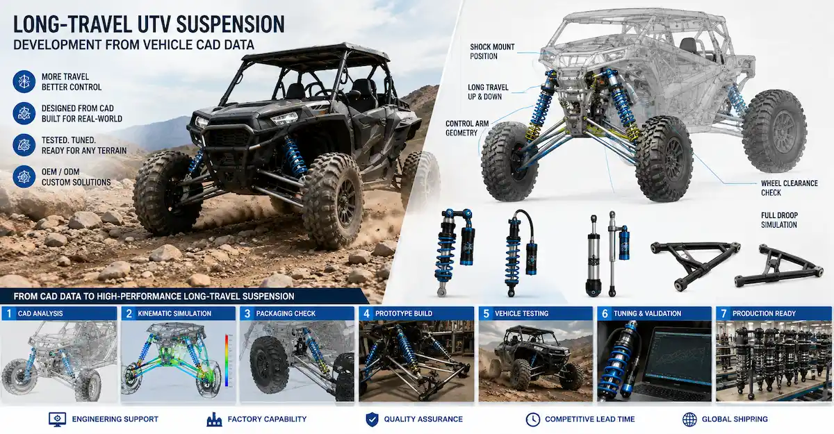
This is closely related to CAD-based suspension development, where digital models are used to check geometry, mounting positions, packaging space, and component relationships before physical prototypes are produced.
What Drawings Can a Suspension Supplier Work From?
Different projects begin with different levels of engineering information.
2D Technical Drawings
A 2D drawing is particularly useful for defining:
- Critical dimensions
- Tolerances
- Materials
- Surface treatment
- Inspection requirements
- Manufacturing notes
The most important requirement is clarity.
The supplier should be able to identify exactly which dimensions are critical and which features are reference information.
3D CAD Files
3D CAD can help with:
- Component geometry
- Packaging
- Interference checking
- Assembly relationships
- Prototype preparation
Common neutral CAD formats used across engineering workflows may include STEP or IGES files, although the exact accepted file format should be confirmed with the supplier.
For technical product definition, ISO 16792 provides guidance for digital product definition data and covers both model-based and combined model/drawing approaches.
Dimensioned Sketches
Early-stage customers may not yet have production drawings.
A dimensioned sketch can still be useful for preliminary discussion when it clearly identifies:
- Overall dimensions
- Mounting positions
- Hole sizes
- Required interfaces
- Key vehicle dimensions
It should normally be refined before final production approval.
Physical Samples Plus Drawings
For reverse-engineering or replacement projects, the strongest starting point may be:
Existing sample + drawing + application information
The sample provides a physical reference, while the drawing establishes the dimensions that both parties agree to control.
What Must Be Confirmed Before Manufacturing Suspension Parts From Drawings?
One of the most common purchasing mistakes is sending a drawing and immediately asking:
“What is the price?”
Before meaningful quotation or manufacturing begins, several technical questions should be resolved.
Dimensions
Confirm:
- Overall length
- Width
- Hole diameter
- Mount spacing
- Wall thickness where relevant
- Interface dimensions
- Component clearance
Tolerances
Not every dimension requires an extremely tight tolerance.
Over-specifying tolerance can increase:
- Machining complexity
- Inspection workload
- Scrap risk
- Manufacturing cost
Under-specifying critical dimensions can create:
- Poor fitment
- Misalignment
- Assembly problems
- Inconsistent production
ISO 129-1 provides general principles for the presentation of dimensions and tolerances on technical product documentation. Buyers who require geometrical tolerancing can also reference ISO 1101, which defines geometrical specification symbols and rules.
The important purchasing principle is to distinguish between critical-to-fit dimensions and dimensions that do not require the same level of control.
Material
A drawing should identify the intended material where material selection affects:
- Strength
- Wear
- Corrosion resistance
- Machining
- Welding
- Surface treatment
If the material is not fixed, the buyer should clarify the required functional objective rather than allowing an unspecified substitution.
Surface Treatment
Suspension components frequently operate in environments involving:
- Water
- Mud
- Dust
- Road debris
- Outdoor exposure
Where surface treatment matters, the requirement should be stated in the technical documentation.
Avoid vague notes such as:
“Good anti-rust treatment.”
A controlled drawing should define the intended process or agreed specification wherever necessary.
Drawing Accuracy vs Manufacturability: Why Both Matter
A technically complete drawing is not automatically an economical production drawing.
This is where manufacturability review becomes important.
A supplier should evaluate whether the specified component can be produced reliably using the proposed process.
Questions can include:
- Is the tolerance realistically achievable?
- Can the selected material be sourced consistently?
- Does the geometry create unnecessary machining complexity?
- Is the component easy to inspect?
- Are there features that may cause assembly difficulty?
- Can the prototype process transition into repeatable production?
This review should not silently change the customer's design.
Instead, the supplier should identify the issue and discuss the proposed engineering change before production.
From Drawing to Suspension Part: A Practical OEM Workflow
1. Drawing and RFQ Review
The buyer submits available technical information.
Useful information includes:
- Drawing files
- CAD models
- Reference samples
- Vehicle application
- Quantity
- Material requirement
- Finish requirement
- Inspection requirement
- Future production estimate
2. Technical Clarification
The supplier reviews unclear or missing information.
Questions may focus on:
- Unspecified dimensions
- Critical tolerances
- Material
- Mounting interfaces
- Application environment
- Drawing revision
This stage is valuable because correcting ambiguity before production is usually easier than correcting physical parts later.
3. Manufacturability Review
The drawing is assessed against available manufacturing processes.
Potential issues should be identified before sample production.
4. Prototype or Sample Production
A small number of components can then be manufactured for evaluation.
This stage gives the buyer a physical reference for:
- Dimensions
- Fit
- Assembly
- Appearance
- Manufacturing feasibility
For complete suspension systems, prototype work can continue through suspension sample development.
5. Dimensional Inspection
Manufactured components should be compared against the agreed drawing.
Critical characteristics may be checked through suitable measurement methods according to the component geometry and required tolerance.
The approval criteria should be defined before production rather than after a disagreement occurs.
6. Assembly and Vehicle Fitment
A component can pass dimensional inspection and still reveal an installation issue at vehicle level.
Fitment evaluation may identify:
- Insufficient clearance
- Incorrect mounting interface
- Unexpected interference
- Alignment problems
7. Drawing Revision
When changes are required, update the drawing rather than relying only on emails or verbal instructions.
The revised document should clearly distinguish the new version from the original design.
8. Pilot and Production Preparation
Once the prototype has been approved, the project can progress toward pilot or repeat production.
The production team should work from the approved revision rather than an earlier prototype drawing.
Drawing Revision Control Is Critical for OEM Purchasing
Revision control is one of the least glamorous but most important parts of custom manufacturing.
Consider a typical situation:
- Revision A is quoted.
- Prototype testing identifies a mounting change.
- Engineering creates Revision B.
- Purchasing sends a new PO.
- Production accidentally uses Revision A.
The result can be an entire batch of unusable components.
A drawing-based OEM workflow should therefore make it clear:
- What is the current revision?
- Who approved it?
- When was it released?
- Which version is used for quotation?
- Which version is used for production?
- Which version is used for inspection?
This creates traceability between engineering and purchasing.
Drawings vs Samples: Which Is Better for Custom Suspension Parts?
Neither is universally better.
They solve different problems.
| Development Input | Advantage | Main Limitation | Best Use |
|---|---|---|---|
| 2D drawing | Clear dimensions and tolerances | Limited 3D context | Manufacturing control |
| 3D CAD | Strong geometry visualization | May lack tolerances/notes | Design and packaging |
| Physical sample | Real component reference | Original specification may be unknown | Replacement development |
| Drawing + sample | Combines control and physical reference | Requires engineering review | Reverse engineering |
| Vehicle CAD + part CAD | Helps interface review | Performance still unvalidated | New vehicle development |
For an OEM buyer, the strongest engineering package is often not one file but a combination of reliable information.
What Should Buyers Check Before Approving Suspension Parts?
Before accepting prototype suspension parts, check more than appearance.
Dimensional Compliance
Verify critical dimensions against the approved drawing.
Interface Fit
Confirm that:
- Holes align
- Bushings fit
- Mounting widths are correct
- Parts assemble without forced installation
Materials and Finish
Confirm agreed:
- Material
- Surface treatment
- Appearance
- Markings where applicable
Revision
Check that the sample was manufactured from the latest drawing.
Functional Validation
For structural suspension components, appropriate application-specific validation may still be required.
For complete shock absorbers, drawing approval alone does not validate:
- Spring rate
- Compression damping
- Rebound damping
- Leakage
- Durability
- Vehicle handling
These need separate engineering and testing work.
How Drawing-Based Sourcing Reduces OEM Purchasing Risk
A clear technical drawing creates an objective reference when discussing:
- Quotations
- Samples
- Quality
- Engineering changes
- Supplier responsibility
Without a controlled drawing, disagreements can become subjective:
“This is not what we wanted.”
With a controlled drawing, the discussion becomes measurable:
“Dimension X is outside the approved tolerance.”
That difference is important for international B2B purchasing where engineering teams and suppliers may work thousands of kilometers apart.
How Bedo Auto Supports Drawing-Based Suspension Development
For buyers developing shock absorbers or custom suspension systems, Bedo Auto can connect drawing review with later prototype-development stages rather than treating the drawing as an isolated document.
Relevant project inputs can include:
- Existing shock absorber samples
- Customer drawings
- CAD files
- Mounting dimensions
- Vehicle information
- Suspension requirements
Buyers can first review Bedo's shock absorber product range to determine whether an existing configuration is suitable.
When an existing product cannot meet the project requirement, drawing review can support a custom development route involving prototype preparation, validation, and production planning.
For projects beginning with incomplete technical documentation, see the Shock Absorber Drawing Service Guide.
For projects moving into physical development, the Shock Absorber Prototype Supplier Guide explains the next stage from engineering information to prototype validation.
What Should You Include in an RFQ for Suspension Parts From Drawings?
A strong RFQ can reduce unnecessary back-and-forth.
Include:
- Latest 2D drawing
- 3D CAD file if available
- Drawing revision number
- Vehicle or application information
- Required material
- Required surface treatment
- Critical tolerances
- Reference sample if available
- Prototype quantity
- Expected production quantity
- Inspection requirements
- Required packaging or identification
- Intended development stage
Do not guess missing technical information simply to complete the RFQ.
Mark unresolved specifications clearly so they can be reviewed with the supplier.
Buyers can send their drawings, CAD files, reference samples, and project requirements through the Bedo Auto contact page.
FAQ
Can suspension parts be manufactured directly from a drawing?
Yes, when the drawing contains sufficient manufacturing information and the supplier confirms that the design is suitable for the intended process. Complex or new parts may still benefit from prototype validation before production.
Can you manufacture suspension parts from a 3D CAD file only?
A 3D model can define geometry, but manufacturing may require additional information such as tolerances, materials, finish requirements, and inspection criteria. The required documentation depends on the component.
Can a suspension part be made from a physical sample without drawings?
A physical sample can be measured and used as a development reference, but creating controlled technical documentation is valuable if the part will later enter repeat production.
What file formats should OEM buyers provide?
2D drawings and neutral 3D CAD formats are commonly useful, but accepted formats should be confirmed with the supplier before sending the project.
Why are tolerances important for suspension parts?
Tolerances define acceptable dimensional variation. Critical mounting and assembly dimensions may need tighter control to maintain fit and repeatability.
Should every dimension have a tight tolerance?
No. Unnecessarily tight tolerances can increase manufacturing and inspection costs. Engineering teams should identify which dimensions actually affect fit, function, or assembly.
Can drawings be modified after the first prototype?
Yes. Prototype evaluation commonly leads to engineering revisions. The updated drawing should receive clear revision control before additional samples or production are released.
Is a CAD model enough to confirm suspension performance?
No. CAD can help confirm geometry and packaging, but vehicle-level performance, damping, spring behavior, durability, and related characteristics require appropriate physical validation.
Can drawing-based projects move into small-batch production?
Yes, after the design and prototype have been approved and the supplier confirms that the manufacturing process can reproduce the required specifications consistently.
What should I send Bedo Auto for a drawing-based suspension project?
Send the latest drawings, CAD data, available reference sample, mounting dimensions, vehicle information, prototype requirements, and expected production plan through the Bedo Auto contact page.
Conclusion
Suspension parts from drawings give OEM buyers a more controlled route to custom development when catalog components cannot meet the required geometry, interface, or vehicle application.
The most important step is not simply sending a CAD file to a factory. Successful drawing-based development requires clear dimensions, realistic tolerances, defined materials and finishes, controlled revisions, prototype verification, and a manufacturing process capable of reproducing the approved design.
2D drawings, 3D CAD, physical samples, and vehicle data each provide different engineering value. Combining them appropriately can reduce ambiguity and help buyers identify problems earlier in the development process.
For complete suspension projects, drawing approval should then connect to prototype and physical validation rather than being treated as final proof of vehicle performance.
If you are developing custom shock absorbers or suspension components from existing drawings, CAD models, or samples, send the available engineering information to Bedo Auto for technical review and prototype-development planning.