
Yes, but the answer depends on what the factory is actually being asked to develop.
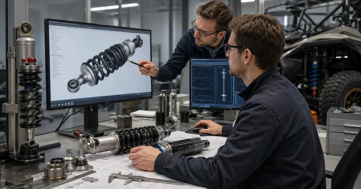
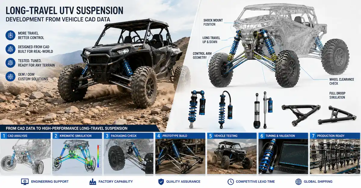
A supplier can use vehicle CAD to study shock mounting positions, suspension hard points, available packaging space, wheel and tire clearance, suspension movement, and the relationship between wheel travel and shock travel. That makes CAD extremely useful for a custom project.
What CAD cannot do by itself is define the final spring and damping specification.
A serious long-travel UTV suspension from CAD data project normally needs both geometry and operating information:
CAD Geometry + Vehicle Loads + Suspension Targets + Prototype Testing
There is another distinction buyers should understand early.
Developing a longer shock absorber is not the same as developing a complete long-travel suspension system.
If the project only requires a shock matched to an already validated long-travel chassis, a shock absorber supplier may be able to work directly from the customer’s CAD geometry and load data.
If the project also requires new control arms, steering links, knuckles, CV axles, chassis hard points, or other suspension components, the work becomes a broader vehicle suspension engineering project.
That difference should be defined before the RFQ is sent.
What Does “Long-Travel UTV Suspension” Actually Mean?
Long travel refers to increased usable wheel movement, not simply a longer shock body.
This matters because buyers sometimes begin a project with a request such as:
“The standard shock is 420 mm. Please make us a 500 mm shock for more travel.”
That approach can create new problems.
A longer shock can move suspension components outside the geometry originally designed for the vehicle. At full bump or full droop, other parts may reach their limits before the shock does.
A long-travel project may therefore require checking:
- Shock mounting points
- Control-arm movement
- Ball-joint angles
- CV-joint operating angles
- Axle plunge
- Tie-rod movement
- Brake hose length
- Tire-to-body clearance
- Tire-to-arm clearance
- Spring compression
- Bump-stop engagement
- Chassis clearance
The useful engineering rule is simple:
More shock length does not automatically create safe additional wheel travel.
Long travel should be designed around the complete suspension kinematics.
What Can a Factory Learn From Vehicle CAD?
A useful CAD package can answer questions that are difficult to solve from photographs or shock dimensions alone.
Suspension Hard Points
CAD can show where the suspension is attached to the chassis and moving components.
Relevant points may include:
- Upper shock mount
- Lower shock mount
- Control-arm pivots
- Knuckle connections
- Tie-rod attachment points
- Relevant axle or driveline interfaces
These locations define how the suspension moves.
Moving even one mounting point can change the relationship between wheel movement and shock movement.
Shock Installation Angle
A shock mounted almost vertically behaves differently from one installed at a substantial angle.
CAD lets engineers see that angle through suspension movement rather than evaluating only the eye-to-eye dimension.
This helps determine how much shock stroke is needed for the desired wheel travel.
Wheel and Tire Envelope
Larger wheel travel means the tire moves through a larger three-dimensional space.
At full compression, the tire may approach:
- Fender structures
- Chassis tubes
- Bodywork
- Suspension arms
At steering lock, the clearance problem can become different again.
CAD allows these conditions to be reviewed before physical parts are produced.
Full Bump and Full Droop Positions
A long-travel system should be reviewed throughout the usable movement range.
Important conditions include:
| Position | What Should Be Checked |
|---|---|
| Full droop | Joint angles, hose length, shock extension, axle limits |
| Ride height | Shock position, sag, ground clearance |
| Partial compression | Progressive clearance and geometry |
| Full bump | Shock compression, tire clearance, bump stop,spring condition |
| Steering + bump | Tire, tie rod and chassis clearance |
| Steering + droop | Joint and linkage clearance |
This is one of the biggest advantages of CAD-led development: obvious packaging conflicts can sometimes be found before prototype tooling or sample fabrication begins.
Is CAD Enough to Calculate the Final Shock?
No.
CAD tells engineers how components are positioned and how they move. It does not tell them everything about the forces involved.
A suspension supplier still needs vehicle data.
At minimum, the buyer should try to provide:
- Vehicle curb weight
- Front and rear axle loads
- Passenger configuration
- Cargo range
- Permanent accessories
- Tire size
- Intended ride height
- Target wheel travel
- Intended terrain
- Typical vehicle speed
- Existing suspension behavior
Without load data, an engineer can understand the geometry but still lack a reliable basis for spring selection and damping development.
That is why:
CAD defines how the suspension moves; vehicle data helps define what that suspension must control.
What CAD Files Should an OEM Buyer Send?
A factory does not always need the complete vehicle CAD assembly.
In many cases, a smaller technical package is enough and can also reduce unnecessary exposure of proprietary vehicle data.
A useful package may contain:
| CAD/Data Item | Purpose |
|---|---|
| Chassis suspension area | Defines mounting structure |
| Upper/lower shock mounts | Defines shock geometry |
| Control arms | Shows suspension movement |
| Knuckle/upright | Helps evaluate wheel path |
| Wheel and tire | Checks clearance |
| Steering linkage | Checks bump/steering movement |
| CV axle where applicable | Checks angle and plunge |
| Existing shock | Establishes baseline |
| Hard-point coordinates | Supports geometry review |
STEP and IGES are commonly exchanged neutral CAD formats, but buyers should confirm which file formats the engineering team can use before transferring data.
For sensitive projects, it is also reasonable to ask:
- Which assemblies are actually required?
- Can hard-point coordinates replace some full CAD models?
- Who needs access to the files?
- How will revisions be controlled?
Providing the minimum useful engineering dataset can protect IP while still allowing the suspension work to move forward.
What Is the Difference Between Shock Development and Full Long-Travel Suspension Development?
This distinction can prevent a great deal of confusion during quotation.
Shock Development From Existing Long-Travel Geometry
The customer has already defined:
- Control arms
- Wheel path
- Chassis hard points
- Axles
- Steering geometry
The supplier is mainly developing the shock and spring package.
The engineering scope may concentrate on:
- Extended length
- Compressed length
- Stroke
- Mounting dimensions
- Spring
- Preload
- Damping
- Reservoir configuration
- Adjustment features
Complete Long-Travel Suspension Development
The target wheel travel cannot be achieved with the existing geometry.
The project may then involve changes beyond the shock absorber, such as:
- Control-arm dimensions
- Mounting locations
- Track width
- Steering linkage
- CV axle requirements
- Brake-line routing
- Chassis interfaces
That project requires broader vehicle engineering capability.
A shock manufacturer should not tell an OEM buyer that a complete vehicle can be converted to long travel merely by extending the shock dimensions.
How Is Shock Stroke Determined From CAD?
The key is the relationship between wheel movement and shock movement.
If the wheel moves through a large distance while the shock moves through a smaller distance, the shock does not need the same physical stroke as the wheel travel.
CAD can be used to observe this relationship across the suspension movement.
The supplier should evaluate the shock at:
- Full droop
- Intended ride height
- Full bump
This establishes the approximate stroke window required by the vehicle geometry.
But the shock should not normally be designed to use every millimeter of physical stroke as uncontrolled vehicle travel.
The suspension system also needs to account for mechanical protection and bump management.
A shock that reaches its internal physical limit before the suspension is safely controlled can be damaged.
Why Does Motion Ratio Matter?
A suspension's motion relationship affects both the shock and spring.
When the wheel moves, the shock may move by a different amount depending on:
- Shock attachment location
- Control-arm geometry
- Shock angle
- Suspension position
That relationship can change through travel rather than remaining perfectly constant.
For the OEM buyer, the practical lesson is more important than the formula:
The same shock and spring can behave differently when installed at different mounting locations.
This is one reason copying a shock specification from another UTV is risky, even if both vehicles have similar weight.
The geometry may not be the same.
Can CAD Determine Spring Rate?
CAD can contribute to spring selection, but it cannot do the job alone.
Spring development should also consider:
- Vehicle mass
- Front/rear weight distribution
- Unsprung and sprung conditions relevant to the design
- Intended ride height
- Desired sag
- Suspension motion relationship
- Payload range
- Passenger load
A spring selected only because it physically fits the shock may not support the vehicle correctly.
For a utility UTV, the challenge becomes greater when the vehicle must work both empty and loaded.
The spring needs enough support for the intended operating condition without making the lightly loaded vehicle unnecessarily harsh.
If the load range is unusually wide, the project may also need to consider:
- Preload adjustment
- Dual-rate or other spring strategies where appropriate
- Different model specifications
The correct answer depends on the vehicle, not a generic “long-travel” spring rate.
Can CAD Determine Damping?
Not completely.
CAD can show shock movement and suspension geometry, but compression and rebound damping should ultimately be developed around dynamic vehicle behavior.
Damping depends on factors such as:
- Vehicle weight
- Spring choice
- Suspension geometry
- Terrain
- Vehicle speed
- Tire behavior
- Payload
- Driver expectations
An initial damping specification can be developed from the engineering data.
The final specification should normally be refined through prototype testing.
That is particularly important for long-travel suspension because the vehicle may operate through a wider movement range and over more demanding terrain than the original setup.
Which Parts Must Be Checked Before Increasing Travel?
Long-travel development is often limited by a component other than the shock.
CV Axles and Joints
More droop can increase joint angles.
The axle may also need sufficient plunge through suspension movement.
Steering Linkage
Tie rods and steering geometry need to remain compatible with the intended movement.
A suspension that gains wheel travel but introduces unacceptable steering behavior has not been successfully developed.
Ball Joints or Spherical Joints
The joint needs sufficient articulation through the new movement range.
Brake Hoses
A hose that is safe at normal ride height can become stretched at full droop.
Tires
Check clearance during:
- Full bump
- Full droop
- Full steering lock
- Combined steering and suspension movement
Springs
At full compression, confirm that the spring is not being driven beyond its usable compressed condition.
Chassis and Mounts
Additional travel or altered leverage can change loads at suspension hard points.
Where a project changes structural components or mounting positions, appropriate structural engineering review may also be necessary.
Does Long Travel Always Improve UTV Performance?
No.
Longer wheel travel can be useful for particular off-road applications, but more travel is not automatically better for every UTV.
There can be trade-offs involving:
- Packaging
- Cost
- Vehicle width
- Steering geometry
- Driveline geometry
- Suspension weight
- Ride height
- Durability requirements
- Maintenance
A slow utility vehicle operating on relatively moderate terrain may not benefit enough to justify a major geometry redesign.
A recreational UTV repeatedly crossing severe terrain may have a much stronger technical reason for increased travel.
The target should therefore be:
Enough usable suspension travel for the application
rather than:
The maximum possible travel
When Can the Existing Suspension Geometry Be Retained?
Sometimes the customer does not need a complete long-travel kit.
If CAD review shows that the existing geometry already has enough safe movement and the current shock is the limiting component, development may concentrate on the shock.
That can reduce:
- Development scope
- Prototype complexity
- New component count
- Project cost
However, this conclusion should come from geometry review rather than assumption.
If the control arms, joints, steering, axle or chassis reach their limits before the target travel is achieved, a shock-only solution is unlikely to be sufficient.
How Should a Factory Develop the First Prototype?
A practical project flow can look like this:
Vehicle CAD Review → Hard-Point Check → Target Travel → Shock Packaging → Load Data → Initial Spring & Damping Specification → Prototype → Installation Check → Vehicle Test → Revision → Pilot Production
The first prototype does not need to be treated as the final production specification.
Its job is to answer engineering questions.
After installation, the buyer should check:
- Ride height
- Sag
- Shock position at rest
- Full bump clearance
- Full droop clearance
- Tire clearance
- Joint articulation
- Brake-line routing
- Steering movement
- Spring condition
- Reservoir or hose routing where applicable
If any geometry issue appears, correct it before pushing the vehicle into demanding dynamic testing.
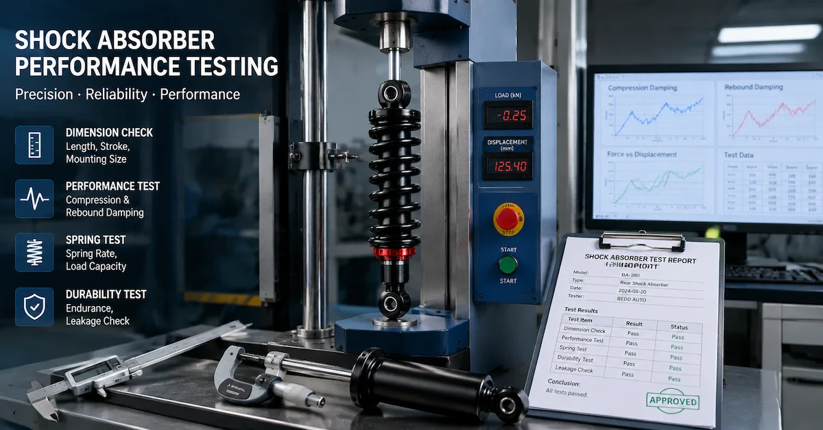
What Should Be Tested on the Vehicle?
The prototype should be evaluated in several real operating conditions rather than one unloaded drive.
| Test Condition | Main Purpose |
|---|---|
| Vehicle at curb condition | Establish baseline |
| Driver only | Evaluate normal ride |
| Typical passenger load | Check sag and balance |
| Typical cargo load | Check working condition |
| High realistic operating load | Confirm usable travel |
| Rough terrain | Evaluate compression control |
| Repeated bumps | Evaluate rebound and recovery |
| Full steering movement | Confirm clearance |
The buyer should document what changed between each test.
If the spring, preload, compression setting and rebound setting are all changed at the same time, it becomes difficult to know which change actually solved the problem.
One controlled revision at a time produces more useful development feedback.
What Information Should I Give the Factory Before Requesting a Quote?
A high-conversion engineering RFQ should contain enough information for the supplier to understand the project before quoting.
Vehicle and CAD Data
Provide the relevant suspension CAD, hard points or technical drawings.
Include:
- Vehicle platform
- Wheelbase
- Track width if relevant
- Wheel and tire size
- Current suspension layout
Weight Information
Provide:
- Curb weight
- Front axle load
- Rear axle load
- Passenger requirements
- Cargo requirements
Existing Suspension
Provide:
- Shock sample if available
- Extended length
- Compressed length
- Stroke
- Mounting dimensions
- Spring information
Long-Travel Target
Explain what you actually want to achieve.
For example:
“The current vehicle has approximately X wheel travel. We want to evaluate additional front and rear travel while retaining the existing chassis hard points if feasible.”
That is far more useful than:
“We need longer UTV shocks.”
Vehicle Use
Describe:
- Utility or recreational application
- Terrain
- Typical speed
- Passenger count
- Cargo
- Duty cycle
Commercial Requirements
Include:
- Prototype quantity
- Pilot quantity
- Estimated production volume
- Target market
- OEM/private-label requirements
- Packaging requirements
A detailed RFQ helps the supplier separate a simple shock-development project from a broader suspension redesign before engineering and tooling costs are discussed.
What Drives the Cost of a CAD-Based Long-Travel Project?
Project cost depends heavily on development scope.
A shock-only project is very different from redesigning several suspension components.
| Project Scope | Relative Complexity |
|---|---|
| New shock for validated geometry | Lower |
| New shock + spring specification | Low to medium |
| Custom reservoir/adjustable shock | Medium |
| Shock + revised mounting geometry | Medium to high |
| Long-travel arms + shock package | Higher |
| Full suspension/steering/driveline revision | Highest |
Other cost drivers can include:
- Number of custom parts
- Prototype quantity
- Number of revision rounds
- Machined components
- Custom spring requirements
- Adjustable damping architecture
- Reservoir architecture
- Special finishes
- Testing requirements
- Production quantity
For procurement teams, the best price comparison is therefore:
Same Engineering Scope + Same Product Specification + Same Prototype Scope + Same Production Requirements
Comparing unit price before those items are aligned can be misleading.
How Do I Evaluate a Factory for a CAD-Based Suspension Project?
Do not evaluate the supplier only by whether it accepts CAD files.
Opening a STEP file is not the same as engineering a suspension.
Ask how the supplier approaches the project.
Useful questions include:
- What CAD information do you need from us?
- Which suspension hard points are required?
- Can you review shock movement from full bump to full droop?
- How will target wheel travel be translated into shock stroke?
- What load information is required for spring selection?
- How is the initial damping specification determined?
- Which clearances should we validate on the first prototype?
- How will vehicle test feedback be converted into revisions?
- Which specification becomes the production reference?
- How will engineering revisions be identified between prototype and production?
A strong response should explain a process.
A weak response usually jumps directly from CAD upload to price.
Should I Send the Factory My Entire Vehicle CAD?
Not necessarily.
For IP-sensitive OEM programs, discuss the minimum data required for the suspension scope.
A supplier may only need:
- Relevant chassis section
- Suspension components
- Wheel/tire envelope
- Shock locations
- Critical interfaces
- Hard-point coordinates
The exact requirement depends on the project.
Before sharing proprietary files, buyers can also clarify:
- Confidentiality procedure
- File-access scope
- Revision naming
- Whether supplier-generated CAD will be returned
- Ownership of custom drawings or tooling where applicable
These commercial and IP questions are easier to settle before development begins than after the prototype has already been built.
How Bedo Auto Fits Into a CAD-Based UTV Project
For a shock absorber or suspension project, the buyer can send Bedo Auto vehicle geometry, CAD or drawings, current shock information, axle-load data, intended wheel travel, terrain, payload, and performance requirements for project-specific discussion.
The useful starting point is not simply a request for a longer shock.
It is a package that explains:
Vehicle Geometry + Current Suspension + Target Travel + Vehicle Load + Application
Depending on project scope, the discussion can then focus on shock dimensions, spring requirements, damping, mounting conditions, reservoir configuration, prototype evaluation, and production requirements.
Buyers can review relevant shock absorber products before preparing the project package.
For a new custom program, send the available CAD, vehicle data, current suspension information, target travel, expected prototype quantity and production volume through the Bedo Auto contact page.
A technically useful inquiry could read:
“We are developing a UTV platform and want to increase usable wheel travel. We can provide suspension CAD, hard-point locations, vehicle weight, axle loads, current shock dimensions, wheel/tire data and target operating conditions.We need to evaluate whether the project can be achieved through shock development or requires changes to the existing suspension geometry.”
That gives an engineering team enough context to start asking the right questions.
FAQ
Can a factory develop long-travel UTV suspension from CAD data?
Yes, if the CAD contains enough suspension geometry and the factory has the relevant engineering and prototype capability. Vehicle weight, axle loads, intended use and physical testing are still needed because CAD alone cannot define the final spring and damping setup.
Is CAD enough to design a long-travel UTV shock?
No. CAD can define geometry, packaging and movement, but the supplier also needs vehicle load and operating information to develop the spring and damping specification.
Can I get more UTV wheel travel by installing a longer shock?
Not necessarily. Control arms, joints, steering, axles, tire clearance and chassis geometry may limit travel before the longer shock reaches its intended range.
What CAD information is most important?
Shock mounting points, suspension hard points, control arms, wheel/tire envelope, relevant chassis geometry, steering components and driveline interfaces are particularly useful.
Does a factory need my complete UTV CAD model?
Not always. For many projects, a reduced suspension assembly plus hard-point data and the necessary vehicle specifications may be sufficient.
Can CAD be used to calculate UTV shock stroke?
Yes, CAD can help determine the relationship between wheel movement and shock movement and therefore support initial stroke selection.
Can spring rate be selected from CAD alone?
No. Geometry is only part of spring selection. Vehicle weight, axle loads, target sag, motion relationship, payload and intended use should also be considered.
Can damping be finalized before vehicle testing?
An initial specification can be developed from engineering inputs, but prototype vehicle testing is important for refining compression and rebound behavior.
What should be checked at full UTV suspension droop?
Relevant checks can include shock extension, joint articulation, CV angle and plunge, brake-hose length, steering linkage, tire clearance and other mechanical limits.
What should I send for a long-travel UTV suspension quotation?
Send relevant vehicle CAD, weight and axle-load information, current shock specifications, wheel and tire data, target travel, terrain, passenger and cargo requirements, current suspension limitations, prototype quantity and expected production volume.
Conclusion
A factory can develop long-travel UTV suspension from CAD data, but CAD should be treated as the geometry foundation of the project rather than the complete engineering answer.
The most useful development chain is:
Vehicle CAD → Hard Points → Suspension Movement → Target Wheel Travel → Shock Stroke → Vehicle Load → Spring & Damping → Prototype → Full Bump/Droop Check → Vehicle Testing → Revision → Production
The biggest mistake is treating long travel as a shock-length problem.
It is a vehicle-system problem.
If the existing control arms, steering, joints, axles and chassis geometry already permit the target movement, a custom shock-and-spring project may be enough. If those parts reach their limits first, broader suspension development is required.
For OEM buyers, that distinction should be made before requesting a quotation. Send the geometry, explain the vehicle load and application, define the target wheel travel, and ask the supplier to identify what can be retained and what genuinely needs to change.
That usually leads to a better prototype, a more comparable quotation, and a much more productive engineering conversation.