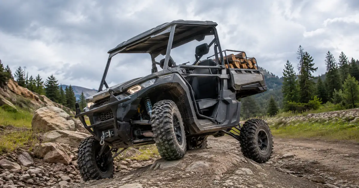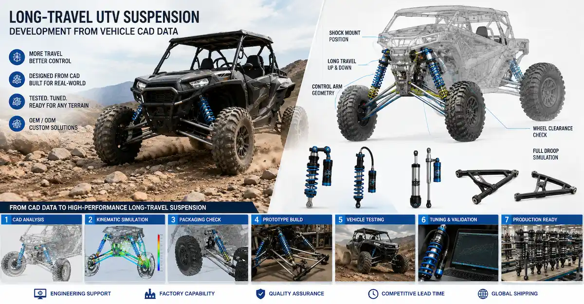

What Is an ATV Suspension Drawing Service?
An ATV suspension drawing service converts vehicle geometry, shock absorber requirements, mounting dimensions, existing samples, sketches, or CAD data into technical documentation that can support custom suspension development.
For an ATV manufacturer, the drawing stage is not simply about producing a visually complete CAD model. The real purpose is to define how the shock absorber and surrounding suspension components fit within the vehicle's mechanical system before prototype manufacturing begins.
A useful ATV suspension drawing may help define:
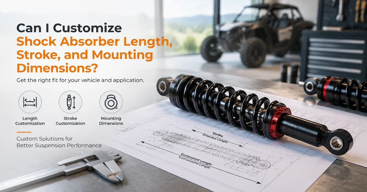
- Shock absorber extended length
- Compressed length
- Stroke
- Upper and lower mounting locations
- Mounting-hole and bushing dimensions
- Shock installation angle
- Spring packaging
- Reservoir location
- Clearance around the A-arms
- Wheel and tire clearance
- Chassis interfaces
- Prototype dimensions and revision status
This makes the drawing a shared engineering reference for the vehicle designer, shock absorber supplier, prototype team, purchasing department, and quality team.
For buyers developing a completely new suspension package, Bedo Auto's CAD-Based Suspension Development content explains how digital geometry can connect with prototype development and later physical validation.
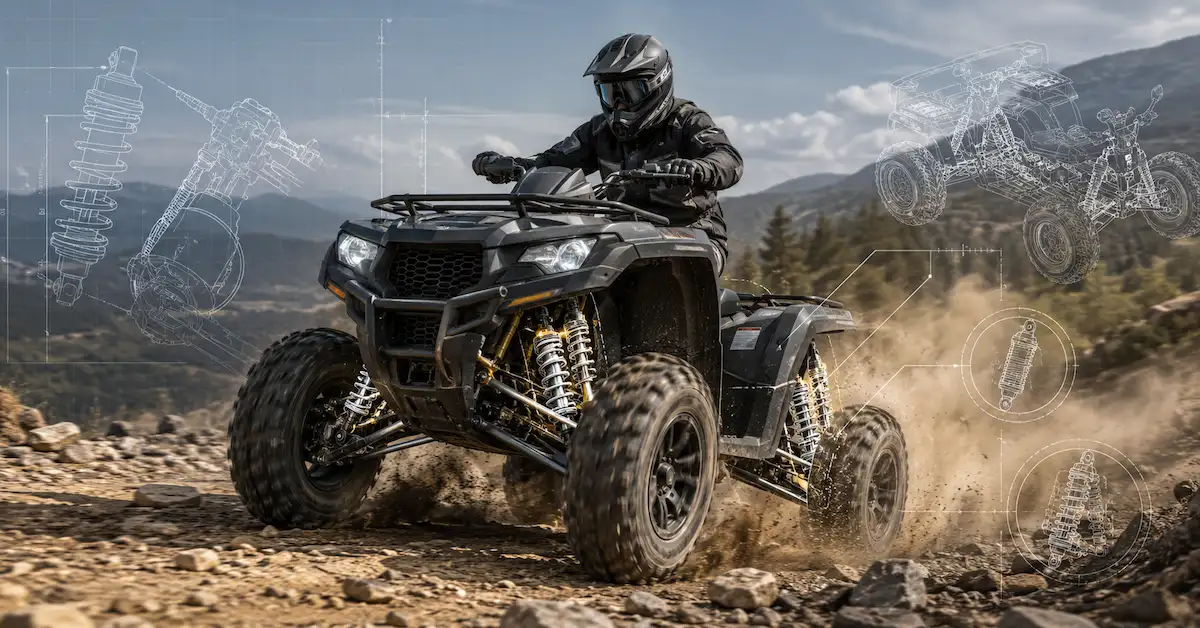
Why ATV Suspension Drawings Need More Than Shock Absorber Dimensions
A common sourcing mistake is to define an ATV shock absorber only by eye-to-eye length.
That information is important, but it does not describe the complete suspension application.
ATV shock movement is connected to the geometry of the chassis, control arms, mounting points, wheel travel, and installation angle. Therefore, two shocks with similar dimensions may not produce the same suspension behavior when installed on different vehicles.
For a new ATV project, engineering review may need to consider:
- Vehicle curb weight
- Maximum loaded weight
- Rider and cargo load
- Front or rear suspension position
- Shock mounting angle
- Wheel travel
- Shock stroke
- Ride height
- Droop and bump conditions
- Spring packaging
- Tire clearance
- Steering clearance
- Drivetrain or CV-joint clearance
- Target terrain
The drawing therefore needs to represent the application, not just the shock absorber as an isolated component.
This is one reason an ATV-specific engineering supplier can provide more value than a general CAD drafting provider.
Who Needs an ATV Suspension Drawing Service?
This service is especially useful for OEM buyers who are developing or modifying an ATV platform.
Typical projects include:
- New recreational ATV development
- Utility ATV suspension development
- Electric ATV projects
- Agricultural ATV applications
- Youth ATV platforms
- Performance or racing ATV projects
- Existing ATV chassis upgrades
- Private-label suspension programs
- Replacement of discontinued shocks
- Reverse engineering from an existing sample
The required engineering depth varies.
A buyer replacing an existing shock with an identical application may only need controlled dimensions and manufacturing documentation.
A manufacturer developing a new ATV platform may need a much broader process involving vehicle geometry, CAD packaging, prototype shocks, spring matching, damping development, testing, and engineering revisions.
What Information Should You Provide for ATV Suspension Drawing Development?
The quality of the drawing depends heavily on the quality of the engineering input.
The supplier should not be expected to finalize a suspension design from a photograph alone.
| Project Input | Recommended Information | Why It Matters |
|---|---|---|
| ATV type | Utility, recreational, racing, electric, etc. | Defines application context |
| Suspension position | Front or rear | Determines installation environment |
| Vehicle weight | Curb and loaded weight | Supports suspension review |
| Payload | Rider, passenger or cargo | Defines working load range |
| Wheel travel | Target vertical wheel movement | Helps relate shock movement to suspension travel |
| Shock extended length | Mount-center reference | Defines full extension |
| Shock compressed length | Minimum length | Defines compression limit |
| Shock stroke | Available damper movement | Supports suspension-travel review |
| Upper mount | Location and interface dimensions | Defines chassis connection |
| Lower mount | Location and interface dimensions | Defines control-arm connection |
| Shock angle | Installed orientation | Influences suspension relationship |
| Wheel/tire size | Tire envelope | Supports clearance review |
| A-arm geometry | Mounting and movement geometry | Supports suspension packaging |
| Spring data | Rate, free length, OD if available | Supports spring development |
| Reference shock | Existing physical unit | Provides dimensional reference |
| Vehicle CAD | Chassis and suspension model | Supports interference review |
| Target terrain | Trail, utility, sand, rock, racing, etc. | Guides later tuning |
If some parameters have not yet been confirmed, they should be marked clearly as open engineering items.
A drawing containing assumed data may look complete while actually increasing development risk.
Which Dimensions Matter Most on an ATV Suspension Drawing?
The exact requirements depend on the vehicle, but several dimension groups are especially important.
Extended and Compressed Shock Length
Extended length determines the shock's maximum installed length.
Compressed length defines the minimum dimension before the shock reaches its mechanical compression limit.
Both should use clearly defined reference points, such as mount center to mount center.
Incorrect definitions can create problems with:
- Suspension droop
- Maximum compression
- Mounting alignment
- Chassis interference
- Tire clearance
Shock Stroke
Shock stroke is not automatically equal to wheel travel.
The relationship depends on suspension geometry and where the shock attaches to the control arm.
For OEM engineering, the drawing should therefore distinguish between:
Shock stroke
and
Wheel travel
rather than treating them as interchangeable values.
Upper and Lower Mounting Interfaces
Critical mount details can include:
- Mounting-hole diameter
- Bushing inner diameter
- Bushing width
- Eye width
- Fork or clevis dimensions
- Bolt position
- Mounting-center location
A dimensional error at the interface may prevent installation even when the main shock body is correct.
Shock Installation Angle
The angle between the shock and suspension movement can influence how shock movement relates to wheel movement.
For drawing review, the important objective is to define the actual installed position rather than assume the shock operates vertically.
Spring and Body Envelope
The drawing should consider enough physical space for:
- Coil spring
- Adjustment collar
- Shock body
- Reservoir
- Hose
- Mounting hardware
This matters because surrounding ATV components may move relative to each other throughout suspension travel.
Why Wheel Travel and Shock Stroke Must Be Reviewed Together
ATV buyers often specify a target wheel travel because it directly relates to vehicle capability.
However, the shock absorber experiences a different movement based on suspension geometry.
A simplified conceptual relationship is:
Wheel Movement → Control Arm Rotation → Shock Mount Movement → Shock Stroke
Therefore, a suspension drawing should not simply assume:
200 mm wheel travel = 200 mm shock stroke.
The actual relationship depends on:
- Control-arm geometry
- Shock mounting point
- Shock angle
- Suspension position throughout travel
For this reason, 3D CAD can be especially useful when the OEM team has chassis and A-arm geometry available.
The model can help engineers review whether the proposed shock length and stroke are geometrically compatible before the first prototype is built.
2D Drawing vs 3D CAD for ATV Suspension Development
Both formats can be valuable, but they serve different purposes.
What 2D Drawings Are Best For
A 2D technical drawing can communicate:
- Critical dimensions
- Tolerances
- Mounting details
- Materials
- Surface treatments
- Manufacturing notes
- Revision information
- Inspection requirements
This is especially useful when the drawing will later support prototype manufacturing or production inspection.
What 3D CAD Is Best For
A 3D model can help review:
- Shock position
- A-arm relationships
- Chassis packaging
- Tire clearance
- Reservoir location
- Hose routing
- Component interference
- Assembly relationships
For an ATV suspension project, this spatial information may reveal problems that are difficult to recognize from a standalone shock drawing.
When Both Should Be Used
For more complex OEM programs, a combined approach is often practical:
3D CAD for geometry and packaging
2D drawings for dimensions, tolerances and production control
The correct documentation depends on the development stage and what the buyer needs to approve.
What Can CAD Check During ATV Suspension Design?
CAD is especially useful for geometric questions.
Suspension Packaging
Engineers can evaluate whether the shock absorber occupies acceptable space throughout the expected vehicle layout.
A-Arm Clearance
The spring, shock body, reservoir, and adjustment components need sufficient space relative to the control arms.
Tire and Wheel Clearance
The wheel and tire envelope may change relative to suspension components during steering and suspension movement.
A static image is not enough to represent every condition.
Chassis Clearance
Upper shock mounts, frame tubes, body structures, and nearby components can influence the available shock package.
Reservoir Placement
Remote-reservoir suspension may require additional review of:
- Reservoir location
- Hose length
- Hose routing
- Brackets
- Service access
- Nearby heat or moving components
These considerations should be addressed before prototype manufacturing where possible.
What CAD and Drawings Cannot Prove
A professionally prepared ATV suspension drawing is still not the same as a validated suspension system.
| Drawing/CAD Can Help Define | Physical Validation Is Needed For |
| Shock dimensions | Compression damping |
| Mount locations | Rebound damping |
| Stroke geometry | Spring behavior |
| A-arm interfaces | Ride comfort |
| Component clearance | Vehicle handling |
| Spring envelope | Thermal behavior |
| Reservoir location | Leakage resistance |
| Production dimensions | Durability |
This distinction is important.
An attractive CAD rendering should never be treated as proof that the ATV will ride, handle, or survive exactly as intended.
Those questions need prototype testing.
Bedo's Suspension Sample Development process provides a useful next step after digital design because it connects drawings with physical samples, validation, optimization, and production preparation.
How Does an ATV Suspension Drawing Project Work?
A practical OEM workflow may include the following stages.
1. ATV Application Review
The supplier first understands the target vehicle.
Questions may include:
- What type of ATV is being developed?
- What is the vehicle weight?
- What payload is expected?
- Is the suspension front or rear?
- What wheel travel is required?
- What terrain will the vehicle operate on?
- Is comfort, utility, or high-speed control the priority?
This creates context for the engineering work.
2. Existing Data Review
The buyer may provide:
- Chassis CAD
- A-arm CAD
- Existing shock drawing
- Reference shock absorber
- Suspension sketches
- Vehicle dimensions
- Installation photos
The supplier should identify contradictions or missing information before moving forward.
3. Preliminary Suspension Layout
The initial layout focuses on major geometry:
- Shock position
- Upper mount
- Lower mount
- Shock length
- Required stroke
- Available spring space
- Reservoir packaging
This stage is primarily about feasibility.
4. Detailed ATV Shock Drawing
Once the basic layout is accepted, the shock absorber and interfaces can be documented in greater detail.
Critical dimensions should be distinguished from reference dimensions.
5. Engineering Review
The buyer and supplier verify:
- Fitment
- Mounting geometry
- Stroke
- Packaging
- Clearance
- Materials
- Required tolerances
Open questions should be resolved or clearly identified.
6. Prototype Manufacturing
A physical sample is then produced from the approved design.
For buyers moving from drawings to physical development, Bedo's Shock Absorber Prototype Supplier Guide explains how prototype work can include drawing review, sample development, spring matching, damping adjustment, and validation.
7. ATV Installation Validation
The prototype should be installed on the actual vehicle or representative test platform where practical.
Engineers can then review:
- Mount fit
- Available travel
- Interference
- Spring clearance
- Reservoir clearance
- Suspension movement
8. Performance Testing
After geometric fit is confirmed, the project can move to performance evaluation.
This may identify requirements for changes to:
- Spring rate
- Preload
- Compression damping
- Rebound damping
- Adjustment range
9. Drawing Revision
Any approved design change should be transferred back into the technical documentation.
10. Pilot and OEM Production
Once the design has been validated, the approved drawing can become part of the manufacturing and inspection reference for future production.
Why Drawing Revision Control Matters for ATV OEM Projects
A prototype project may change several times before final production.
For example:
Revision A
Initial ATV shock layout
Revision B
Lower mount position adjusted after vehicle fitment
Revision C
Reservoir orientation changed for clearance
Revision D
Production-approved configuration
If production later uses Revision B instead of Revision D, the supplier can manufacture a dimensionally accurate part that is still technically wrong.
A controlled OEM workflow should therefore identify:
- Drawing number
- Revision number
- Release date
- Approval status
- Matching CAD revision
- Prototype batch
- Production reference
This is particularly important when engineering, purchasing, and production teams are located in different countries.
Can an ATV Suspension Drawing Be Created From an Existing Shock?
Yes.
An existing ATV shock absorber can provide useful reference information for:
- Overall length
- Stroke
- Mounting structure
- Spring dimensions
- Shock body
- Reservoir arrangement
- Adjustment components
A physical sample is especially valuable when the original CAD or technical drawing is unavailable.
However, the supplier should first determine whether the new ATV uses the same:
- Vehicle weight
- Suspension geometry
- Payload
- Wheel travel
- Mounting angle
- Terrain
- Performance target
If those factors change, simply copying the original shock may not be appropriate.
This is where a drawing service should connect with suspension engineering rather than simple reverse measurement.
What Should Buyers Check Before Approving an ATV Suspension Drawing?
Before releasing a drawing for prototype manufacture, use a structured review.
Installation Geometry
Confirm:
- Upper mount position
- Lower mount position
- Extended length
- Compressed length
- Shock angle
Suspension Movement
Confirm:
- Required shock stroke
- Target wheel travel
- Droop condition
- Compression condition
Clearance
Review:
- A-arm clearance
- Tire clearance
- Chassis clearance
- Spring clearance
- Reservoir clearance
- Hose routing where applicable
Interfaces
Confirm:
- Mounting-hole diameter
- Bushing dimensions
- Bolt size
- Eye or fork width
Documentation
Check:
- Drawing revision
- CAD revision
- Materials
- Surface treatment
- Critical tolerances
- Unresolved engineering items
Do not approve a drawing simply because its visual presentation looks finished.
Common ATV Suspension Drawing Mistakes
Choosing Shock Length Without Reviewing Suspension Geometry
A shock length that fits statically may still create problems at full droop or compression.
Better approach: review extended and compressed conditions with the suspension geometry.
Confusing Wheel Travel With Shock Stroke
They are not automatically equal.
Better approach: define both values separately.
Ignoring Tire Clearance
ATV tires can occupy a large movement envelope, especially when suspension travel and steering are considered together.
Better approach: include the wheel and tire package in CAD review where possible.
Copying an Existing Shock to a Different ATV
Similar appearance does not guarantee equivalent application requirements.
Better approach: review vehicle mass, suspension geometry, load, and use case.
Finalizing CAD Before Prototype Feedback
Prototype installation frequently reveals issues that were not obvious during the first design stage.
Better approach: treat drawing revision as part of normal engineering development.
How to Choose an ATV Suspension Drawing Supplier
An OEM buyer should evaluate more than CAD software capability.
Ask whether the supplier understands:
- ATV suspension applications
- Shock absorber geometry
- Control-arm interfaces
- Wheel travel
- Spring packaging
- Mounting constraints
- Prototype development
- Damping tuning
- Testing
- OEM production
A supplier capable of supporting the full development path can reduce handoffs between separate drawing, prototype, testing, and manufacturing vendors.
A practical development route is:
ATV Requirement → CAD/Drawings → Prototype → Vehicle Fitment → Suspension Testing → Revision → Production
For projects requiring broader engineering support, Bedo's Suspension Design Partner Guide explains how suspension design can be connected with later prototype and production work.
How Bedo Auto Supports ATV Suspension Drawing Development
Bedo Auto's suspension-development workflow can connect drawing review with physical shock absorber development rather than treating drawings as the final deliverable.
For an ATV OEM project, available inputs may include:
- Existing shock absorber
- Vehicle CAD
- Customer 2D drawings
- Mounting dimensions
- Vehicle weight
- Suspension requirements
- Target performance information
The development process can then continue into:
- Drawing review
- Suspension design
- Prototype manufacturing
- Spring development
- Damping adjustment
- Testing
- Engineering revisions
- Small-batch validation
- OEM production
Buyers can also review Bedo's shock absorber product range to understand existing suspension configurations before deciding whether a fully custom ATV design is necessary.
If your engineering data has already been approved and the next requirement is manufacturing from technical documentation, see Suspension Parts From Drawings.
What Should You Include in an ATV Suspension Drawing RFQ?
A useful RFQ should give the supplier enough context to understand both the component and the vehicle.
Include available information such as:
- ATV type and application
- Front or rear suspension
- Vehicle curb weight
- Maximum loaded weight
- Desired ride height
- Target wheel travel
- Existing shock extended length
- Existing compressed length
- Required shock stroke
- Upper mounting dimensions
- Lower mounting dimensions
- Shock installation angle
- Wheel and tire dimensions
- A-arm CAD or drawings if available
- Chassis CAD if available
- Existing shock absorber sample
- Spring information
- Terrain and use case
- Prototype quantity
- Expected future production volume
If some parameters are unknown, identify them as open items for engineering review.
You can send available drawings, CAD files, reference samples, and ATV requirements through the Bedo Auto Contact Page.
FAQ
What is an ATV suspension drawing service?
An ATV suspension drawing service prepares or reviews technical suspension documentation using vehicle geometry, shock absorber dimensions, CAD files, physical samples, and OEM requirements to support prototype and production development.
Can you create an ATV suspension drawing from an existing shock absorber?
Yes. An existing shock can provide dimensional and structural reference data. If the new ATV has different weight, suspension geometry, wheel travel, or performance targets, those differences should also be reviewed.
What dimensions are most important for an ATV shock absorber drawing?
Important parameters commonly include extended length, compressed length, stroke, upper and lower mounting dimensions, shock angle, spring envelope, and reservoir clearance.
Is shock stroke the same as ATV wheel travel?
Not necessarily. Wheel movement and shock movement depend on suspension geometry, mounting position, and shock angle. The two values should be defined separately.
Do I need vehicle CAD for an ATV suspension drawing?
Not always. A project can begin from drawings, dimensions, sketches, or physical samples. Vehicle CAD becomes particularly valuable when packaging, suspension geometry, and interference need detailed review.
Can 3D CAD check tire and A-arm clearance?
CAD can help review available space and component relationships when accurate vehicle geometry is available. Physical prototype and vehicle validation are still important before production approval.
Can an ATV suspension drawing determine the correct spring rate?
A drawing can document a spring specification and physical envelope, but the correct spring rate also depends on vehicle weight, load, suspension geometry, ride-height target, and application.
Can CAD determine compression and rebound damping?
CAD geometry alone cannot prove damping performance. Compression and rebound characteristics require separate suspension engineering and physical testing.
What happens after the ATV suspension drawing is approved?
For a custom project, the next stages commonly include prototype manufacturing, ATV installation verification, testing, design revision if required, and production preparation.
How do I start an ATV suspension drawing project with Bedo Auto?
Prepare your existing drawings, CAD files, reference shock, vehicle weight, wheel travel, mounting dimensions, ATV application, and performance requirements, then submit the information through the Bedo Auto Contact Page.
Conclusion
An ATV suspension drawing service is most valuable when it connects digital engineering documentation with the actual geometry and development requirements of the ATV.
A useful drawing should clearly define shock absorber dimensions, mounting interfaces, stroke, installation position, spring and reservoir packaging, and other critical information while identifying which performance characteristics still require prototype validation.
For ATV OEM projects, the strongest workflow is not:
Drawing → Production
but rather:
Vehicle Requirements → CAD/Technical Drawing → Engineering Review → Prototype → ATV Fitment → Testing → Revision → Production Approval
This approach allows engineering teams to identify geometric, fitment, and documentation problems before larger manufacturing commitments are made.
Bedo Auto supports suspension projects through drawing review, custom shock absorber development, prototype manufacturing, spring and damping optimization, testing, and production preparation.
If you are developing a new recreational, utility, electric, or specialty ATV platform, send the available vehicle geometry, suspension drawings, CAD data, reference shock absorber, and project requirements through the Bedo Auto Contact Page for engineering review.