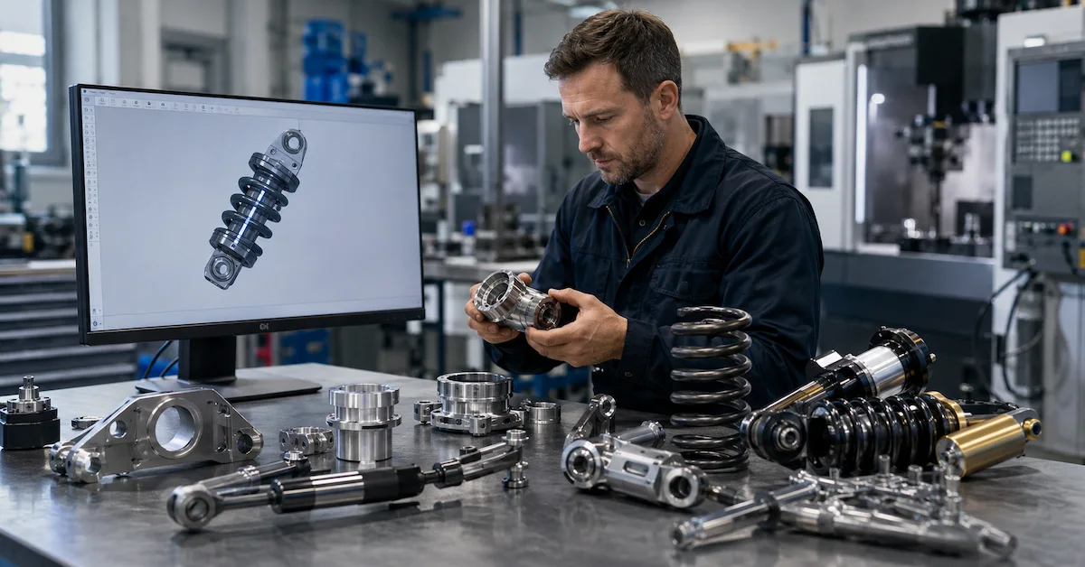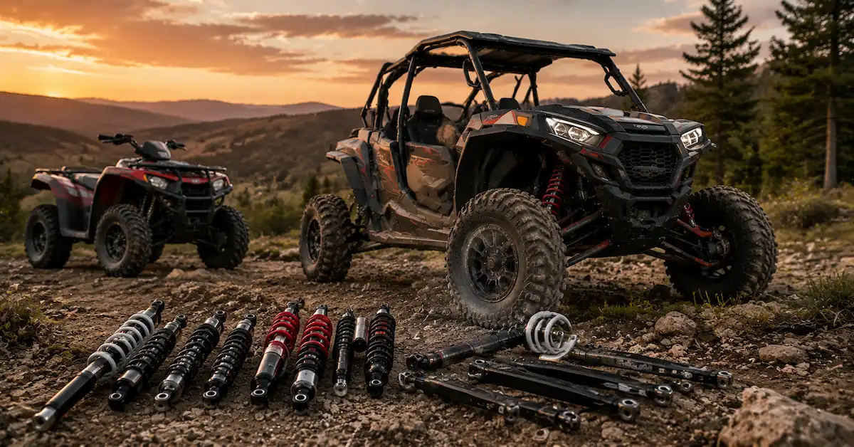

Yes. A capable suspension supplier can use 3D CAD files to develop custom shock absorbers, but a CAD model is normally the starting point rather than the complete production specification.
For an OEM suspension project, engineers may also need to confirm:
- Extended length
- Compressed length
- Stroke
- Mounting dimensions
- Critical tolerances
- Vehicle weight
- Payload
- Suspension position
- Spring requirements
- Compression and rebound targets
- Intended terrain
- Expected production volume
The most reliable development path is:
3D CAD → Engineering Review → Technical Clarification → Prototype → Vehicle Validation → Engineering Revision → Production
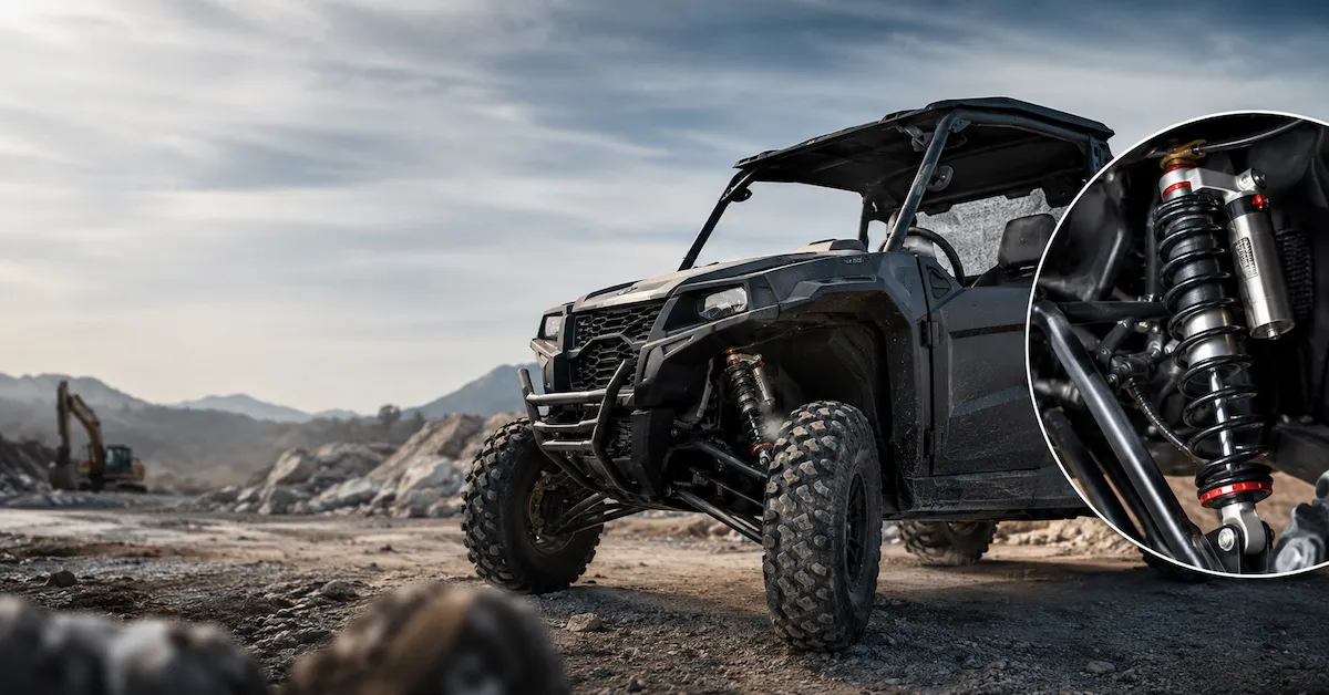
This is especially important for ATV, UTV, off-road,and specialty vehicle projects where physical fitment alone does not guarantee acceptable suspension performance.
A professional supplier should therefore do more than open a CAD file and quote a price. The engineering team should understand what the shock absorber must do on the vehicle and identify missing information before prototype production begins.
Why a 3D CAD Model Alone May Not Be Enough
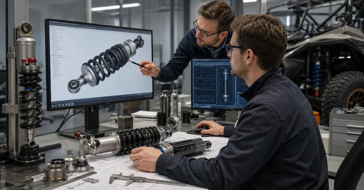
A 3D CAD model is extremely useful because it can communicate product geometry and installation relationships more clearly than photos or basic measurements.
However, many CAD files do not contain every engineering detail required to manufacture and validate a shock absorber.
| 3D CAD May Define | Engineering Still Needs to Confirm |
|---|---|
| Overall geometry | Critical tolerances |
| Mounting locations | Material requirements |
| Packaging space | Surface treatment |
| Shock orientation | Extended and compressed length |
| Component relationships | Usable stroke |
| Installation envelope | Spring specification |
| Basic interfaces | Damping target |
| Vehicle structure | Load and operating conditions |
The key distinction is:
3D CAD defines where the shock absorber fits; engineering data defines how the shock absorber needs to perform.
For this reason, a supplier that immediately treats the CAD geometry as a production-ready specification may overlook important development risks.
What Should You Send With Your 3D CAD File?
The more complete the technical package, the more useful the engineering review will be.
For a custom shock absorber project, OEM buyers should provide as much of the following information as possible.
| Project Information | Why It Matters |
|---|---|
| 3D CAD model | Defines geometry and packaging |
| 2D technical drawing | Defines dimensions and tolerances |
| Existing shock sample | Provides a physical baseline |
| Vehicle type | Defines application |
| Front or rear position | Defines suspension role |
| Vehicle weight | Supports spring development |
| Payload | Defines operating load |
| Extended length | Confirms fitment |
| Compressed length | Defines travel limit |
| Stroke | Defines shock movement |
| Mounting dimensions | Controls installation |
| Existing spring data | Provides a performance baseline |
| Terrain or use case | Defines operating conditions |
| Current suspension problem | Defines development direction |
| Performance target | Defines desired improvement |
If some parameters are not yet confirmed, identify them as engineering questions instead of guessing values.
That gives the supplier a clearer basis for technical discussion.
Do You Also Need a 2D Drawing?
In many OEM projects, yes.
A 3D model is excellent for geometry, packaging, and component relationships, but a controlled 2D technical drawing may be better for defining production-critical information such as:
- Dimensions
- Tolerances
- Thread details
- Materials
- Surface finish
- Heat treatment
- Inspection points
- Special notes
A strong development workflow often uses both:
3D CAD for geometry and engineering review
and
2D drawings for manufacturing control
This combination also makes revision management easier when the design changes during prototype development.
Which CAD Formats Can a Suspension Supplier Use?
CAD capability depends on the supplier's engineering software and internal workflow.
Common engineering formats may include:
- STEP / STP
- IGES / IGS
- Parasolid
- Native CAD files
- Other agreed neutral formats
Before sending the project, ask the supplier which file formats its engineering team can review directly.
Do not assume that being able to open a CAD file means the supplier can fully evaluate it.
The more important questions are:
- Can the engineers identify missing information?
- Can they review manufacturability?
- Can they evaluate mounting relationships?
- Can they give technical feedback before prototyping?
What Should the Supplier Check During CAD Engineering Review?
A professional suspension supplier should review more than the shape of the part.
Packaging and Clearance
The engineering team should evaluate whether the proposed shock absorber fits within the available vehicle space.
Important areas may include:
- Chassis clearance
- Tire clearance
- Control arm clearance
- Spring clearance
- Reservoir position
- Full compression clearance
Interference that is not obvious in a static view may appear when the suspension moves through its full travel.
Mounting Geometry
Important mounting details include:
- Upper mounting point
- Lower mounting point
- Eye width
- Hole diameter
- Fork or clevis geometry
- Mount orientation
Small dimensional errors can create installation problems even if the general CAD model looks correct.
Shock Travel
Engineers should confirm:
- Extended length
- Compressed length
- Stroke
- Available vehicle travel
- Risk of mechanical bottoming
- Risk of topping out
The shock absorber should not become the unintended mechanical travel limit unless the suspension has been designed that way.
Manufacturing Feasibility
The factory should also evaluate:
- Machining requirements
- Assembly access
- Component interfaces
- Realistic tolerances
- Material availability
- Production repeatability
A useful engineering review should identify potential issues before the prototype is made.
How Does 3D CAD Shock Absorber Development Work?
A structured process helps reduce development risk.
Step 1: Receive CAD and Vehicle Data
The supplier receives available project information such as:
- 3D CAD files
- 2D drawings
- Existing shock data
- Vehicle weight
- Payload
- Suspension position
- Performance targets
Step 2: Engineering Review
The engineering team evaluates:
- Geometry
- Fitment
- Mounting
- Travel
- Manufacturability
- Missing technical information
Questions should be resolved before prototype production whenever possible.
Step 3: Technical Clarification
The buyer and supplier confirm unresolved items such as:
- Unknown dimensions
- Spring requirements
- Vehicle loading
- Damping objectives
- Materials
- Surface treatments
This stage is important because inaccurate assumptions can become expensive after samples are manufactured.
Step 4: Prototype Specification
The confirmed engineering information is converted into a controlled prototype specification.
This may include:
- Drawings
- Revision number
- Shock dimensions
- Spring specification
- Damping configuration
- Component requirements
Step 5: Prototype Manufacturing
The supplier manufactures the initial development samples.
The purpose is to validate the engineering assumptions, not simply to produce a visually finished product.
Step 6: Vehicle Testing and Engineering Revision
The prototype should be evaluated on the target application where appropriate.
Feedback may involve:
- Fitment
- Ride height
- Sag
- Load support
- Bottoming
- Compression behavior
- Rebound behavior
- Clearance
The engineering team then determines what needs to change.
Step 7: Production Release
Once the design is approved, the supplier should lock:
- Final CAD revision
- Final 2D drawing
- Spring specification
- Damping configuration
- Materials
- Inspection requirements
- Approved reference sample
Only then should the product move into controlled production.
Can CAD Files Be Used to Customize Shock Absorber Dimensions?
Yes.
A CAD model can be extremely useful when developing custom dimensions.
Depending on the project, a custom shock absorber may involve changes to:
- Extended length
- Compressed length
- Stroke
- Shock body dimensions
- Rod dimensions
- Mounting width
- Eye dimensions
- Fork or clevis interfaces
- Reservoir position
However, dimensional changes should not be made independently.
For example, increasing shock length may affect:
- Suspension travel
- Ride height
- Control arm position
- Tire clearance
- Full compression geometry
A professional supplier should therefore evaluate the dimensions within the complete suspension layout.
Can Spring Rate Be Developed From a 3D CAD File?
Not from the CAD model alone.
CAD geometry may help engineers understand:
- Shock position
- Installation angle
- Packaging
- Suspension relationships
But spring development usually also requires vehicle and load data.
Important inputs include:
- Vehicle weight
- Front/rear weight distribution
- Passenger load
- Cargo load
- Suspension geometry
- Motion ratio where relevant
- Target ride height
- Intended vehicle use
Spring rate should not be selected simply by making the spring "harder" or "softer."
If the Spring Is Too Soft
Possible results include:
- Excessive sag
- Frequent bottoming
- Poor cargo support
- Reduced usable suspension travel
If the Spring Is Too Stiff
Possible results include:
- Harsh ride
- Reduced compliance
- Poor traction
- Limited suspension movement
The goal is to match the spring to the actual vehicle application.
Can Damping Be Designed From a 3D CAD Model?
A CAD model can help define the physical shock absorber package, but it does not provide enough information by itself to establish the correct damping characteristics.
Damping development may require:
- Vehicle weight
- Spring specification
- Suspension geometry
- Terrain
- Vehicle speed and usage
- Performance target
- Prototype test feedback
Compression Damping
Compression damping influences how the suspension resists movement when the wheel moves upward relative to the chassis.
It can affect:
- Impact control
- Bottoming resistance
- Vehicle body movement
Rebound Damping
Rebound damping controls how the suspension extends after being compressed.
It can affect:
- Suspension recovery
- Tire contact
- Vehicle stability
The correct damping target should be developed together with the spring and vehicle application.
Why Is Prototype Development Essential After CAD Review?
A design that fits correctly in CAD may still behave differently on the real vehicle.
That is why:
CAD Fitment ≠ Vehicle Validation
A prototype allows OEM buyers to verify:
- Physical installation
- Mount alignment
- Clearance
- Shock travel
- Spring behavior
- Ride height
- Load support
- Damping response
A typical development sequence may be:
Prototype V1 → Vehicle Test → Engineering Feedback → Revision B → Prototype V2 → Approval
Not every project needs multiple rounds, but the supplier should have a clear process for revisions if testing identifies a problem.
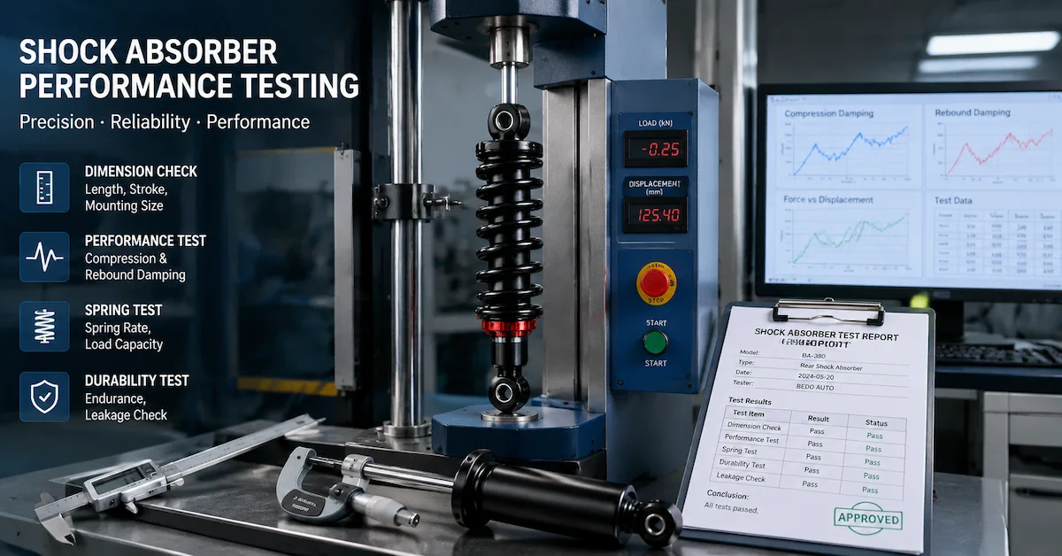
What Should Be Tested Before the Design Is Approved?
Testing scope should be defined according to the actual project.
| Validation Area | What to Confirm |
|---|---|
| Dimensions | Length, stroke,mounting dimensions |
| Fitment | Installation and clearance |
| Spring | Sag and load support |
| Function | Smooth movement and leakage |
| Damping | Compression and rebound behavior |
| Vehicle performance | Application-specific response |
| Manufacturing | Production repeatability |
Some verification may be carried out by the manufacturer.
Other testing may require the actual vehicle and therefore be completed by the OEM, brand, or vehicle development team.
A trustworthy supplier should clearly explain which responsibilities belong to each side.
How Should CAD and Engineering Revisions Be Controlled?
Revision control is one of the most important parts of OEM suspension development.
Suppose Prototype V1 requires changes to:
- Mount width
- Spring rate
- Stroke
- Damping
The supplier should not simply "remember" those changes.
The updated product should receive controlled technical documentation.
Important revision-control items include:
- CAD revision
- 2D drawing revision
- Prototype version
- Spring specification
- Damping configuration
- Approved components
- Approval date
- Reference sample
The final production order should reference an approved engineering revision, not simply:
"Make it the same as the last sample."
That greatly reduces the risk of outdated specifications entering production.
Engineering Suspension Supplier vs Standard Parts Supplier
Not every suspension supplier needs to provide full engineering development.
For standard replacement products, that may not be necessary.
For custom OEM projects, however, the difference becomes important.
| Capability | Engineering Supplier | Standard Parts Supplier |
|---|---|---|
| CAD review | Supported | Limited |
| Vehicle-data analysis | Supported | Limited |
| Custom dimensions | Supported | Limited |
| Spring development | Project-based | Limited |
| Damping development | Project-based | Limited |
| Prototype revisions | Supported | Limited |
| Revision control | Important | Basic |
| OEM production | Suitable | More replacement-focused |
The correct supplier depends on the project.
If the design is already fully validated, standard manufacturing may be sufficient.
If the suspension still requires engineering development, buyers should look for a supplier that can participate in the technical process.
What Questions Should OEM Buyers Ask Before Sending CAD Files?
Before starting a project,ask:
- Can your engineering team review 3D CAD files?
- Which CAD formats can you work with?
- Do you also require a 2D technical drawing?
- Can you identify missing technical information?
- Can you review manufacturing feasibility?
- Can you produce prototypes from our CAD model?
- Can you revise the prototype after vehicle testing?
- How do you manage CAD and drawing revisions?
- Can you develop vehicle-specific spring specifications?
- Can you support damping changes when required?
- Can you support pilot production before mass production?
- How do you ensure production matches the approved prototype?
The answers help distinguish an engineering partner from a supplier that simply accepts CAD files for quotation.
What Should an RFQ for CAD-Based Shock Absorber Development Include?
A high-quality RFQ should combine engineering and commercial information.
Vehicle Information
Provide:
- Vehicle type
- Vehicle platform
- Front or rear position
- Vehicle weight
- Payload
Engineering Information
Provide:
- 3D CAD model
- 2D drawing
- Existing shock sample
- Extended length
- Compressed length
- Stroke
- Mounting details
Performance Information
Explain:
- Current suspension problem
- Desired improvement
- Intended terrain
- Expected operating conditions
Commercial Information
Provide:
- Prototype quantity
- Pilot quantity
- Initial production requirement
- Forecast volume
- Branding requirements
- Packaging requirements
This information enables the supplier to provide a more useful engineering evaluation and quotation.
How Bedo Auto Supports 3D CAD Shock Absorber Development
Bedo Auto supports OEM suspension projects that begin with:
- 3D CAD models
- Technical drawings
- Existing shock absorber samples
- Vehicle requirements
Depending on the project,development support can include:
- CAD and drawing review
- Existing sample evaluation
- Custom shock absorber development
- Dimension customization
- Suspension spring development
- Prototype manufacturing
- Engineering revisions
- Testing support
- Small-batch validation
- Production preparation
Applications include:
- ATV
- UTV
- Off-road vehicles
- Specialty vehicles
Buyers can review Shock Absorber Products for existing product references.
For related development workflows, see:
For a CAD-based OEM project, send your available 3D model, 2D drawings, vehicle weight, payload, existing shock data, target performance requirements, prototype quantity, and expected production volume for engineering evaluation.
FAQ
Can a suspension supplier develop shock absorbers from 3D CAD files?
Yes.A capable supplier can use 3D CAD data as the starting point for engineering review and prototype development, but additional vehicle and production information is usually required.
Is a 3D CAD model enough to manufacture a shock absorber?
Not always. Critical dimensions, tolerances, materials, spring requirements, damping targets, and vehicle application data may also need to be confirmed.
Do I need a 2D drawing if I already have a 3D CAD model?
A 2D technical drawing is useful for defining critical dimensions, tolerances, materials, finishes, and manufacturing requirements that may not be explicit in the 3D model.
Can a supplier customize shock absorber dimensions from my CAD model?
Yes, subject to engineering feasibility and the vehicle's suspension geometry.
Can spring rate be developed from CAD files?
CAD data alone is generally insufficient. Vehicle weight, load, suspension geometry, and ride-height targets are also important.
Can damping be customized from a CAD model?
CAD helps define physical geometry, but damping development also requires vehicle, spring, terrain, and performance information.
Can a factory produce a prototype before mass production?
Yes. An OEM-focused suspension supplier should ideally support prototype development so fitment and performance can be validated before production.
What happens if the prototype needs changes?
Test feedback should be converted into a controlled engineering revision before the next prototype or production version is manufactured.
Can CAD-based suspension projects start with low volumes?
Yes, depending on tooling, materials, components, and project complexity. Prototype and pilot quantities should be discussed separately from production MOQ.
What should I send for an OEM shock absorber quotation?
Send the CAD model, available drawings, vehicle information, shock dimensions, load conditions, performance target, prototype quantity, and expected production volume.
Conclusion
A suspension supplier can develop shock absorbers from 3D CAD files, but the CAD model should be treated as the beginning of the engineering process rather than the complete production specification.
Successful OEM development requires:
3D CAD + Vehicle Data + Engineering Review + Prototype Validation + Revision Control + Production Management
For ATV, UTV, off-road, and specialty vehicle projects, the ideal workflow is:
CAD Review → Technical Clarification → Prototype → Vehicle Testing → Engineering Revision → Production
A strong suspension supplier does more than reproduce CAD geometry. It helps connect that geometry to vehicle requirements, manufacturing feasibility, suspension performance, and reliable production.
For a new CAD-based suspension project, provide your 3D model together with available drawings, vehicle information, current suspension data, performance goals, and expected quantities so the engineering team can evaluate the project before prototype development begins.