
What Should I Verify Before Approving a Suspension Drawing?
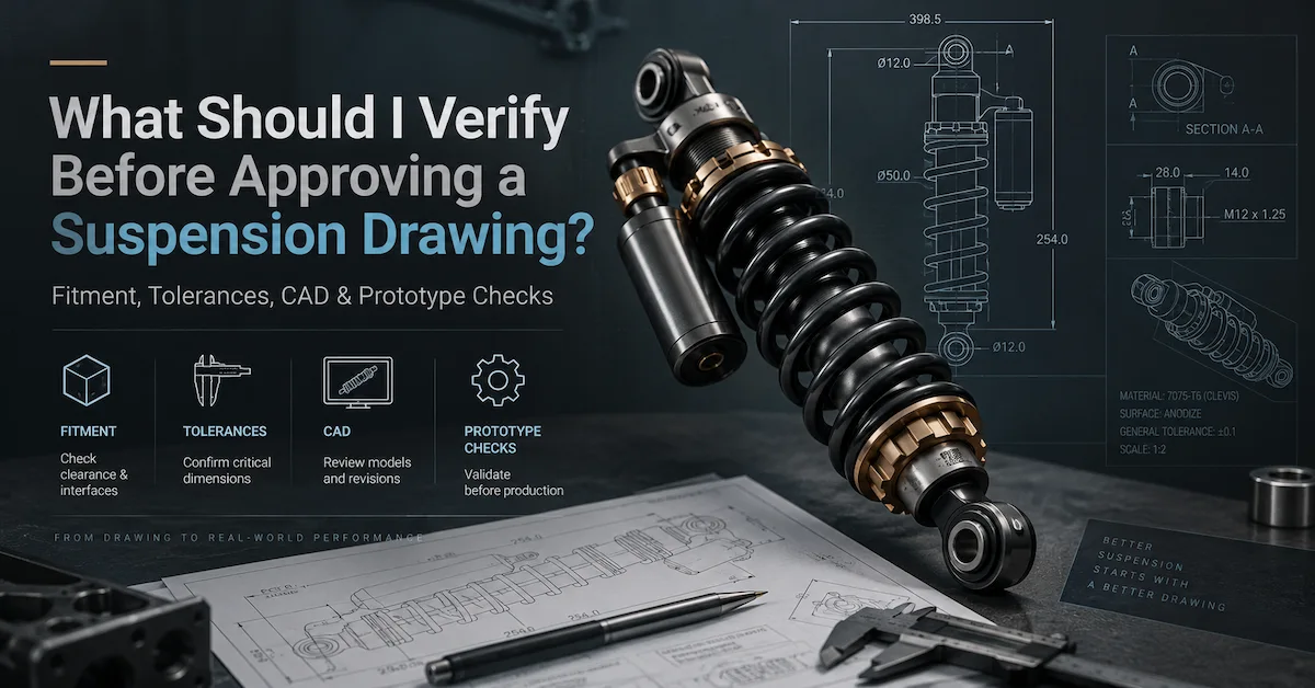
Before approving a suspension drawing, verify that the document clearly defines the product’s installation dimensions, movement limits, upper and lower mounting interfaces, component envelopes, critical tolerances, materials or finishes where required, revision status, and any specifications that remain dependent on prototype testing. BEDO’s shock absorber drawing service uses a similar approval logic: extended and compressed lengths, stroke, mounting references, bushings, spring clearance, reservoir clearance, tolerances, and unresolved engineering items should be reviewed before prototype production. A suspension drawing approval should therefore mean “this document is sufficiently defined for the next agreed engineering stage,” not “the complete suspension has already been proven to perform correctly.”
First Confirm What the Drawing Is Being Approved For
A drawing can be released for quotation, prototype manufacture, pilot production, or full production. These are not equivalent approvals. A quotation-stage drawing may intentionally contain supplier-proposal items, while a production drawing should normally reflect the configuration already validated and accepted for manufacturing. Buyers should therefore state the document status explicitly—such as For Engineering Review, For Prototype, or Released for Production—instead of allowing an email saying “approved” to cover every future stage.
A practical suspension drawing approval system should separate three decisions: the drawing is complete enough to manufacture the prototype; the resulting prototype meets fitment and performance requirements; and production units can reproduce the accepted design. BEDO’s technical drawing guidance similarly separates drawing approval from prototype and production approval.
Verify Extended Length, Compressed Length, and Stroke
The drawing should define extended and compressed installation lengths using the same clear reference system. For eye-mounted shocks, this may involve mounting centers; for clevis, stem, pin, or other structures, the relevant axes or contact surfaces must be explicitly identified. Avoid approving a generic “overall length” unless everyone understands exactly what it measures.
Effective stroke should also be stated separately. Buyers should not assume that subtracting two catalog dimensions always gives the correct usable stroke, particularly when bump stops, internal travel limits, or undefined measurement references are involved. Shock stroke should also remain separate from wheel travel, which depends on vehicle suspension geometry.
Use this first-dimensional checklist during suspension drawing approval:
| Drawing item | What to verify before approval | Main risk if unclear |
|---|---|---|
| Extended length | Defined reference points and operating condition | Shock does not match droop geometry |
| Compressed length | Same references at approved compression limit | Mechanical bottoming or insufficient bump travel |
| Effective stroke | Explicit usable damper movement | Wrong travel assumption |
| Units | mm/inch system clearly identified | Conversion and production errors |
| Measurement datum | Stable reference used throughout drawing | Supplier and buyer measure differently |
| Tolerance | Functional limit where required | Fitment or consistency problems |
BEDO’s current shock absorber technical drawing guide also prioritizes extended/compressed references, stroke, mounting interfaces, envelopes, and functional tolerances.
Review Upper and Lower Mounting Interfaces Separately
A shock absorber is not approved for fitment merely because the mounting bolt passes through the eye. Verify the complete upper and lower interfaces independently. Important fields may include mounting-hole diameter, sleeve inner and outer diameter, mounting width, bushing dimensions, clevis spacing, threads, spacers, orientation, and any articulation requirement.
This matters because two products can share the same mounting-hole diameter and stroke while still requiring different brackets. BEDO’s ATV shock absorber fitment guide specifically emphasizes mounting widths, sleeves, bushings, spacers, compressed dimensions, body clearance, and suspension movement rather than treating a common bolt size as proof of compatibility.
Before approval, ask:
- Are upper and lower mounts definitely identical, or have they been copied from one another for convenience?
- Are widths measured across the correct assembled surfaces?
- Are bushings and sleeves included in the stated dimensions?
- Is the mount orientation defined?
- Does the interface have enough articulation for the target suspension movement?
- Are the vehicle bracket dimensions confirmed?
Check the Complete Shock Envelope, Not Only the Main Cylinder
A technical drawing should communicate the space occupied by the assembled product. This may include the main shock body, spring, preload collars, seal head, mounting eyes, adjusters, piggyback reservoir, hose fittings, or other protruding components.
A shock can satisfy its mounting-center dimension yet still interfere with a control arm, chassis member, tire, brake line, or vehicle bodywork. For a performance shock, adjustment knobs can create an additional packaging issue that is invisible if only the main tube diameter is dimensioned.
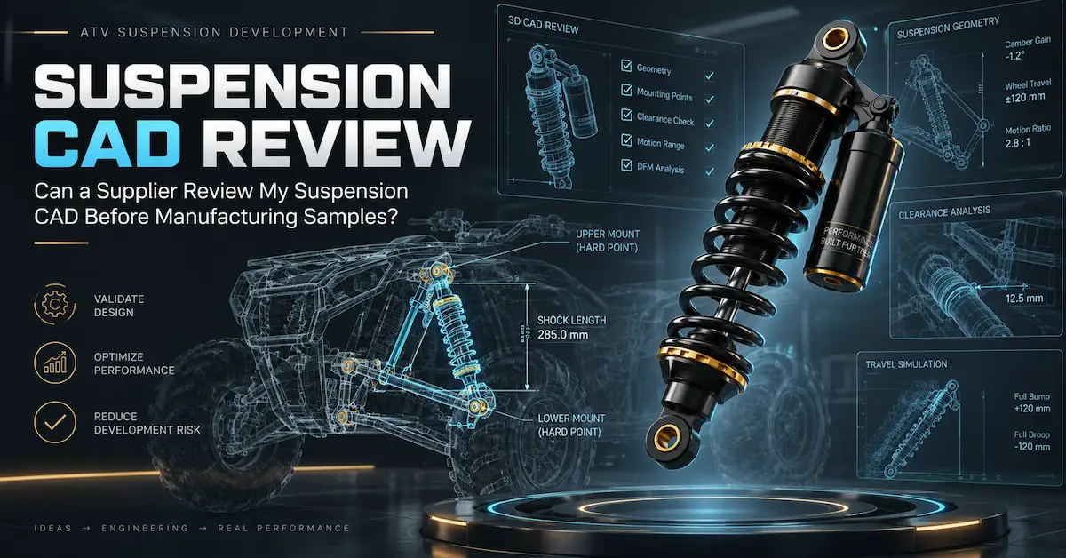
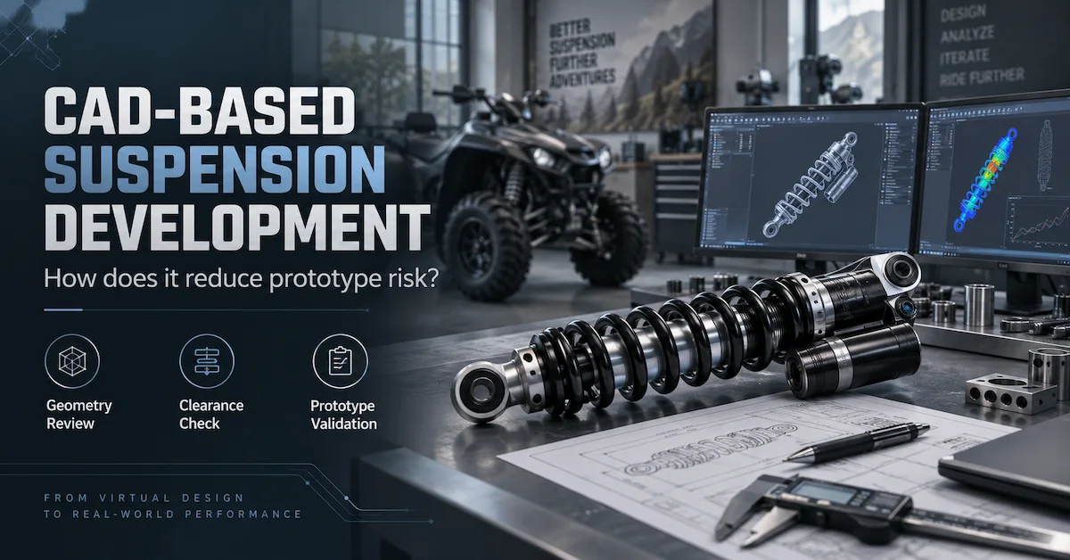
For packaging-sensitive projects, connect the technical drawing to a relevant CAD-based suspension development review. BEDO’s CAD guidance specifically recommends checking body, spring, reservoir, chassis, and nearby-component clearance before approval.
Verify Full Bump and Full Droop Against the Drawing
The drawing describes the component, but approval should also consider where that component will operate. Review the shock in the suspension at ride height, full bump, and full droop where project geometry is available.
At full bump, verify that the shock is not unintentionally becoming the mechanical stop before the vehicle reaches its intended bump limit. Check tire, spring, body, reservoir, chassis, and control-arm clearance.
At full droop, review shock extension, spring seating, joint movement, reservoir hose movement, and other suspension components that may reach their limits first.
For geometry-sensitive projects, the drawing alone is insufficient. BEDO’s CAD development guidance separates geometry, vehicle interfaces, engineering status, and performance requirements and explicitly recommends identifying which dimensions are confirmed versus pending prototype validation.
Verify Spring Dimensions and Reference the Performance Specification
If the product is a coilover shock, the drawing should identify the spring geometry required for assembly and packaging. Depending on the project, this can include free length, inner or outer diameter, seat dimensions, installed condition, adjustment range, and spring identification.
However, do not confuse geometric spring data with spring performance. Spring rate and load-deflection behavior are performance specifications and should either appear clearly on the approved product documentation or be referenced through a controlled spring specification.
A drawing showing a 70 mm diameter red spring does not prove its rate or load capability. If spring selection remains part of prototype development, label it accordingly rather than silently turning an estimated value into an approved production requirement.
Do Not Approve an Undefined Preload Setting
Where the design includes threaded preload adjustment, establish a reference condition. This can help the supplier and buyer reproduce the same setup during testing and prevent different prototype evaluations from being performed with different spring positions.
The relevant drawing or linked setup specification may need to identify:
- initial spring position;
- preload measurement reference;
- acceptable adjustment range;
- minimum thread engagement where relevant;
- lock-ring arrangement;
- reference configuration used for testing.
If preload remains a tuning variable, distinguish the prototype setting from the final customer adjustment range.
Verify Reservoir and Hose Information Where Applicable
A piggyback or remote-reservoir shock requires additional drawing review. For piggyback designs, check reservoir position, diameter, length, orientation, and surrounding clearance. For remote reservoirs, review reservoir mounting details, hose connection points, fitting orientation, hose-length reference, and packaging requirements.
CAD review can then determine whether the hose and reservoir clear moving components. The drawing and CAD should agree on orientation.
Do not approve a reservoir purely because it fits at static ride height. It should remain compatible throughout the vehicle movement that the project requires.
Review Critical Tolerances Instead of Tightening Every Dimension
A production drawing needs tolerances, but tighter is not automatically better. Excessively restrictive tolerances can increase machining time, inspection effort, cost, and scrap without adding functional value.
During suspension drawing approval, identify dimensions where variation directly affects:
- mounting fit;
- alignment;
- suspension movement;
- seal interfaces;
- component assembly;
- spring seating;
- reservoir connections;
- adjuster operation.
Then ask how the tolerance will actually be inspected.
For example, a mounting-width dimension and the vehicle bracket opening should be reviewed together. Approving each nominal dimension individually without evaluating their tolerance stack can still create interference in the worst-case combination.
Confirm Materials Without Guessing from Appearance
The drawing should clearly distinguish between verified material requirements and supplier proposals. Never approve an alloy or steel specification merely because the sample “looks aluminum” or “looks like hardened steel.”
If material is already fixed, verify:
- material designation;
- applicable component;
- relevant condition or heat-treatment requirement where specified;
- referenced internal specification if one is used.
If material is not yet approved, use a status such as Supplier Proposal Required rather than adding a technical-looking grade without evidence.
This is particularly important when drawings are created from physical samples. BEDO’s sample-to-drawing guidance notes that physical measurement can recover geometry but does not automatically recover original material properties, hydraulic specification, tolerances, or design intent.
Verify Surface Finish and Cosmetic Requirements Separately
Surface treatment can affect corrosion resistance, appearance, dimensions, and branding, but the drawing should distinguish cosmetic requirements from functional claims.
Specify known requirements such as finish type, appearance zone, approved color, or logo placement where necessary. If corrosion performance matters, reference the applicable validation requirement rather than assuming a named coating automatically guarantees a particular test result.
For private-label products, keep artwork approval linked to—but separate from—the technical suspension drawing approval. A correct logo does not authorize production if the mounting width or spring specification is still unresolved.
Confirm That CAD and 2D Drawings Describe the Same Product
When both CAD and drawings exist, compare their current revisions before approval. BEDO’s 2D drawings and 3D CAD guide emphasizes that geometry packages still need manufacturing review and that drawing approval should be separated from prototype and production approval.
Create a file register such as:
| Document | Revision | Status | Purpose |
|---|---|---|---|
| Shock assembly CAD | Rev C | Current | Geometry/package |
| Shock technical drawing | Rev D | Current | Prototype manufacture |
| Spring specification | Rev B | Pending prototype | Spring configuration |
| Damping specification | Prototype 02 | Pending validation | Performance |
| Vehicle CAD | Rev F | Reference | Installation review |
| Prototype test plan | Rev A | Released | Acceptance criteria |
If the CAD and drawing disagree, keep prototype release on hold until engineering resolves the difference.
Check Whether Critical Features Are Actually Manufacturable
A drawing can be geometrically correct and still contain difficult manufacturing features.Before approval, ask the manufacturer to conduct a feasibility review covering machining access, forming requirements, clamping surfaces, assembly sequence, component interfaces, material availability, tolerance realism, and inspection access.
BEDO’s drawing-based suspension development process specifically places manufacturing feasibility analysis between customer drawing and production. The page notes that unrealistic tolerances, difficult machining, material issues, and assembly problems can create higher cost and inconsistent production if they are not addressed before manufacturing.
An OEM buyer should therefore ask not only:
“Can you manufacture this drawing?”
but also:
“Which features are difficult to manufacture repeatedly, and what change would you recommend?”
Verify How Every Critical Requirement Will Be Inspected
Do not approve an important requirement that nobody has defined how to inspect. The drawing or its linked quality plan should connect functional features with practical measurement methods.
A simple control structure is:
Critical Feature → Manufacturing Operation → Inspection Stage → Measurement Method → Acceptance Limit
Some features are easiest to inspect before final assembly. Others, such as overall mounting length or final mounting width, can be verified on the completed shock.
For custom suspension, this planning matters because a prototype can be carefully hand-built while production requires repeatable inspection across many units.
Separate Geometry Approval From Spring and Damping Approval
One of the most important approval boundaries is recognizing what the drawing proves.
A drawing can define:
- geometry;
- mounting interfaces;
- component envelopes;
- materials;
- tolerances;
- assembly references.
It cannot by itself prove:
- correct ride comfort;
- correct spring rate;
- correct compression damping;
- correct rebound damping;
- long-term durability;
- real vehicle handling.
BEDO’s drawing-service documentation explicitly states that a technical drawing alone cannot guarantee ride comfort, damping, durability, vehicle handling, or production consistency; these require prototype and testing evidence.
This distinction protects buyers from approving a technically complete document and mistakenly treating it as a fully validated suspension system.
Define What the First Prototype Must Prove
Before signing the drawing for prototype manufacture, write down the purpose of the sample.
A prototype approval plan can include:
| Prototype check | What the sample should demonstrate |
|---|---|
| Dimensional inspection | Product matches drawing |
| Vehicle installation | Upper/lower interfaces fit |
| Full bump/droop | Required movement is available |
| Body/spring clearance | No unintended interference |
| Ride height/sag | Spring setup is appropriate |
| Damping | Target behavior is achieved |
| Leakage | Assembly remains sealed |
| Reservoir/hose | Packaging and routing work |
| Adjustment | Controls operate as intended |
| Manufacturability | Product can move toward repeat production |
BEDO’s prototype-related content uses a development sequence in which drawing review leads to prototype, testing, revision, approval, and then production rather than moving straight from drawing to mass manufacturing.
Use the Drawing as the Baseline for Prototype Changes
If testing produces an approved change, revise the engineering documents.
For example, if vehicle testing shows that a lower mounting width needs modification, do not ask the workshop to “remember the new width next time.” Update the drawing, revise the CAD if affected, identify the new sample revision, and record why the change occurred.
Otherwise, the project can end with three different products:
- the CAD design;
- the official drawing;
- the physical prototype that actually works.
Production must not be forced to guess which one is correct.
Compare Drawing Approval, Prototype Approval, and Production Approval
These three release points answer different questions:
| Approval stage | Main question | What it should not imply |
|---|---|---|
| Drawing approval | Is the technical definition ready for the agreed next stage? | That dynamic performance is proven |
| Prototype approval | Does the physical product meet defined requirements? | That production is automatically repeatable |
| Production approval | Can the approved configuration be made consistently? | That future undocumented changes are permitted |
Keeping these stages separate significantly reduces risk for OEM and private-label buyers.
Consider Cost Before Freezing Unnecessary Complexity
Once a drawing is released, later dimensional and component changes can require new prototypes, machining work, tooling or fixtures, testing, and schedule changes.
Before approval, ask the manufacturer which features drive cost. Determine whether they are function-critical or merely preferences.
Potential cost drivers can include:
- unusual machining;
- custom mounting hardware;
- unnecessarily tight tolerances;
- specialized materials;
- complex reservoirs;
- multiple adjusters;
- unique finishes;
- low-volume proprietary components.
Do not remove a necessary feature simply to reduce cost, but resolve optional complexity before prototypes and tooling have already been purchased.
Clarify Ownership, Revision Rights, and Final Deliverables
Before commissioning a custom development project, agree who owns or controls the final drawing and CAD, what editable formats will be supplied, who can revise the document, how changes are approved, and whether the manufacturer may use the design for other customers.
The words OEM and ODM do not automatically answer these questions.
For projects containing proprietary geometry, also agree how customer CAD, samples, and technical documents will be handled before sharing them.
What Should You Send BEDO Before Requesting Drawing Approval?
BEDO manufactures shock absorbers and suspension springs and describes engineering support for drawing-, CAD-, and sample-based projects. For a useful review, send the latest drawing, corresponding CAD where relevant, target vehicle application, reference sample if available, mounting interfaces, vehicle/load information, required spring and damping status, prototype objective, and expected purchasing quantity. BEDO’s custom suspension development files guide provides a practical structure for organizing those files.
A useful BEDO review request should ask engineering to classify each item as:
Confirmed – ready for release.
Supplier Proposal – manufacturer recommendation required.
Pending Validation – requires prototype/test result.
Revision Required – drawing must be changed before release.
This turns drawing approval into a controlled engineering process rather than a simple signature.
Frequently Asked Questions
1. Is a Complete-Looking Drawing Ready for Approval?
Not necessarily. Check measurement references, tolerances, mounting interfaces, materials, revision status, unresolved engineering items, and the purpose of the drawing before approving it.
2. Do I Need Both Extended and Compressed Length?
For custom shock development, both are important because they define different suspension limits. They should use consistent measurement references and be reviewed together with effective stroke.
3. Should I Approve Spring Rate on the Same Drawing?
It can be stated directly or referenced through a controlled spring specification. If the rate is still being developed, mark it pending validation rather than treating an estimate as final.
4. Can CAD Replace the Technical Drawing?
That depends on the agreed information workflow. CAD is useful for geometry and packaging, while drawings commonly define dimensions, tolerances, notes, and inspection requirements. If model-based definition is used instead, agree exactly where these requirements are stored. See BEDO’s CAD guide.
5. Should Materials Be Approved Before the Prototype?
Known material requirements should be documented before manufacture. Where the supplier is expected to recommend a material, identify it as an engineering proposal and approve it before it becomes a production requirement.
6. Can I Approve the Drawing Before Damping Is Final?
Potentially, if the document is explicitly approved only for the relevant prototype stage and damping remains a controlled open item. The approval status should make that limitation clear.
7. Does Drawing Approval Mean the Shock Is Ready for Bulk Production?
No. The prototype still needs the required dimensional, fitment, performance, and other validation, followed by production-release controls.
8. What Happens If the Supplier Finds a Manufacturing Problem After Approval?
The manufacturer should document the issue and propose a change. Engineering should review its effect, update the controlled files, and determine whether prototype or testing work must be repeated.
9. Should I Approve a Drawing Created from a Physical Sample?
Yes only after distinguishing actual design requirements from wear, damage, and unknown internal specifications. BEDO’s sample-to-drawing guide explains why a physical sample is an engineering reference rather than a complete original specification.
10. What Is the Safest Approval Sequence?
Use Application Requirements → Drawing/CAD Review → Manufacturability Review → Drawing Release → Prototype → Vehicle/Test Validation → Revision → Pilot Production → Production Release. This keeps technical documentation, physical validation, and manufacturing approval separate.
Conclusion
A reliable suspension drawing approval should confirm more than whether the drawing looks complete. Verify extended and compressed references, stroke, upper and lower mounting interfaces, body and spring envelopes, reservoir packaging, tolerances, materials, document revisions, manufacturability, and inspection requirements. Just as importantly, identify which spring, damping, durability, and vehicle-performance questions still require prototype validation rather than embedding assumptions into a production drawing. The safest process is Drawing Review → Manufacturability Review → Prototype Release → Vehicle/Test Validation → Controlled Revision → Production Approval. BEDO supports suspension development from drawings, CAD files, and physical samples. To review your project before prototype manufacturing, contact BEDO with the current drawing, corresponding CAD or sample information, vehicle application, load requirements, and expected quantities so unresolved items can be identified before final suspension drawing approval.