
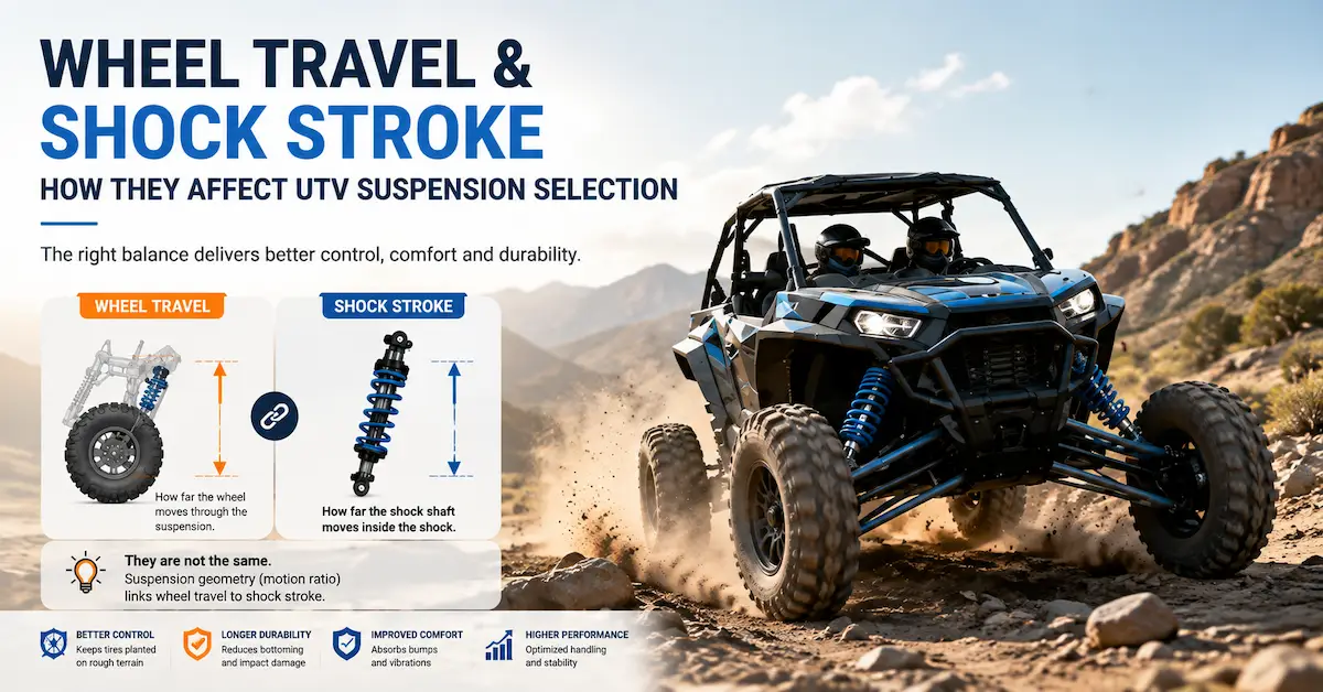
UTV wheel travel and shock stroke are related, but they are not the same measurement.
Wheel travel describes how far the wheel moves through the suspension's usable range. Shock stroke describes how far the shock absorber itself moves between its extended and compressed positions.
Those two distances are rarely identical.
A UTV can have 300 mm of wheel travel without using a 300 mm shock stroke. Suspension geometry, shock mounting position, control-arm length, shock angle, and motion ratio determine how much shock movement is required to control that wheel movement.
This distinction matters when an OEM buyer is selecting a replacement shock, developing a custom suspension, changing ride height, or planning a long-travel UTV.
Choosing by extended shock length alone is not enough.
Choosing by wheel travel alone is not enough either.
The useful engineering sequence is:
Wheel Movement → Suspension Geometry → Shock Movement → Required Stroke → Spring → Damping → Clearance → Prototype Validation
That sequence gives a supplier much more useful information than simply requesting a “longer” or “heavy-duty” shock.
What Is UTV Wheel Travel?
Wheel travel is the amount of suspension movement available at the wheel.
It is commonly discussed as the distance between the wheel's full-droop and full-compression positions.
In real suspension geometry, however, the wheel does not necessarily move in a perfectly straight vertical line. It follows a path defined by the control arms, trailing arms, links, knuckle, and chassis hard points.
For purchasing and engineering discussions, wheel travel therefore represents the usable movement of the wheel through the suspension range rather than the length of one suspension component.
A larger wheel-travel figure can provide more room for the suspension to absorb uneven terrain, but the number alone does not tell you whether a suspension will perform well.
Useful travel also depends on whether the vehicle has sufficient:
| Factor | Why It Matters |
|---|---|
| Compression control | Helps manage bump and impact movement |
| Rebound control | Controls how the wheel returns after compression |
| Spring support | Holds vehicle load at the intended ride height |
| Ground clearance | Determines chassis position over terrain |
| Joint articulation | Allows suspension movement without binding |
| Tire clearance | Prevents contact through bump and steering |
| Driveline clearance | Protects CV joints and axles |
| Shock stroke | Gives the damper enough movement to control the suspension |
A large advertised travel number is therefore not automatically a better suspension specification.
The travel needs to be usable.
What Is Shock Stroke?
Shock stroke is the usable movement of the shock absorber shaft or damper mechanism between the shock's extended and compressed positions.
For many conventional eye-to-eye shock designs, the nominal stroke is related to the difference between extended and compressed dimensions. Exact measurement methods should still follow the supplier's drawing because mounting hardware, bump stops, internal construction, and design details can affect how dimensions are specified.
For example, a shock might have:
| Parameter | Example Only |
|---|---|
| Extended eye-to-eye length | 480 mm |
| Compressed eye-to-eye length | 350 mm |
| Nominal dimensional difference | 130 mm |
That does not mean the UTV has only 130 mm of wheel travel.
The suspension geometry may turn 130 mm of shock movement into considerably more movement at the wheel.
This is where motion ratio becomes important.
Why Aren't Wheel Travel and Shock Stroke the Same?
The shock usually mounts somewhere between the suspension pivot and the wheel.
It may also be installed at an angle.
Because of that geometry, the wheel can move farther than the shock.
Imagine pushing down on the end of a long lever while measuring movement closer to its pivot. The outer end can move a large distance while the inner measurement point moves less.
A suspension behaves in a similar way.
The exact relationship depends on:
Control-arm geometry + shock mounting point + shock angle + suspension position
This means two UTVs with the same wheel travel may require different shock strokes.
It also means two vehicles using shocks with the same stroke can have different wheel-travel figures.
That is why copying a shock specification from a visually similar vehicle is risky.
What Is Motion Ratio?
Motion ratio describes the relationship between wheel movement and shock movement.
There is one important problem in industry discussions: different engineers and suppliers sometimes express the ratio in opposite directions.
One person may define it as:
Wheel Travel ÷ Shock Travel
while another may define it as:
Shock Travel ÷ Wheel Travel
Both conventions can appear in engineering work.
For an RFQ, do not send only “motion ratio = 2.5.”
State the definition.
For clarity, this article will use:
Wheel-to-Shock Travel Ratio = Wheel Travel ÷ Shock Stroke
If the wheel moves 300 mm while the shock moves 120 mm:
300 ÷ 120 = 2.5
The wheel-to-shock travel ratio is therefore 2.5:1 under that simplified example.
Real suspension geometry can be progressive or nonlinear, so the effective relationship may change through travel.
That is why CAD or physical measurement through several suspension positions is more useful than relying on one calculated number.
Why Does Motion Ratio Affect Shock Selection?
Motion ratio changes how much the shock moves for a given amount of wheel movement.
It also affects the forces and velocities the shock and spring experience.
Suppose two UTVs have the same vehicle weight and similar wheel travel.
Vehicle A moves its shock significantly during wheel movement.
Vehicle B moves its shock much less for the same wheel displacement.
Those two vehicles should not automatically use the same spring and damping setup.
Vehicle B's suspension geometry may require the shock assembly to generate different forces because the damper acts through a different mechanical leverage relationship.
This is why suspension suppliers need more than:
“My UTV weighs 700 kg and has 300 mm of travel.”
A better engineering package includes shock mounting geometry or CAD.
How Does Shock Angle Change the Effective Suspension?
Shock angle matters because the shock does not always move in the same direction as the wheel.
A shock installed close to the direction of suspension movement uses its stroke differently from one installed at a significant angle.
As the shock becomes more inclined, a portion of wheel movement may translate into less movement along the shock axis.
That affects effective:
- Shock stroke use
- Spring behavior at the wheel
- Damping behavior
- Packaging
- Clearance
For an OEM project, the shock angle should be checked at more than ride height.
The angle can change through bump and droop.
A CAD model can make this easier to evaluate.
For buyers developing a new platform, the previous guide on long-travel UTV suspension from CAD data explains why suspension hard points, shock mounting position, tire clearance, and full-bump/full-droop geometry should be reviewed together.
How Much Shock Stroke Does a UTV Need?
There is no universal stroke value for a UTV.
The required shock stroke should come from the intended wheel movement and the actual suspension geometry.
The process normally starts with three positions:
Full Droop → Ride Height → Full Compression
The supplier or vehicle engineer then evaluates how the shock length changes between those positions.
That tells you how much movement the shock must accommodate.
But there is another important point.
The normal operating suspension should not casually depend on violently reaching the shock's internal mechanical limit.
The complete suspension system may require appropriate bump management, droop control, or other mechanical protection depending on the design.
A shock should control suspension motion, not become the accidental structural stop for every extreme condition.
What Happens if UTV Shock Stroke Is Too Short?
A shock with insufficient usable stroke can restrict the suspension before the wheel reaches its intended movement.
Possible results include reduced usable wheel travel, premature shock bottoming, harsh impact behavior, and additional load being transferred into the shock mounts.
Suppose the suspension geometry could safely provide 280 mm of wheel movement, but the selected shock reaches full compression much earlier.
The vehicle does not truly have access to that full intended travel.
The shock becomes the limiting component.
The buyer may experience this as a “stiff suspension” or “hard bottoming problem” even though the real issue is dimensional compatibility.
Spring rate changes cannot solve insufficient shock stroke.
Damping changes cannot create missing stroke either.
The geometry and shock dimensions need to match first.
What Happens if the Shock Is Too Long?
A longer shock is not automatically safer.
An excessive extended length may allow the suspension to droop farther than other components can tolerate.
Potential limitations can come from CV joints, ball joints, spherical joints, tie rods, brake hoses, axle plunge, control-arm contact, or other components.
Likewise, an unsuitable compressed length may allow the shock to reach an internal limit before the vehicle's bump-management system is working as intended.
This is why an OEM buyer should provide both:
Extended requirement + compressed requirement
not simply:
“Please add 50 mm to the shock.”
A dimensional change should be checked through the complete suspension range.
Does a Longer Shock Increase Wheel Travel?
Sometimes, but not by itself.
A longer or longer-stroke shock can increase available travel only when the rest of the suspension geometry can safely use that additional movement.
For example, the shock may no longer be the limiting factor, but the CV joint could become the new limit.
Or the tire may contact the chassis at full bump.
Or the upper ball joint may reach its articulation limit.
Or a brake hose may become stretched at droop.
The correct long-travel question is therefore:
Which component currently limits suspension travel?
Only after identifying that limit should the shock specification be changed.
Wheel Travel vs Shock Stroke: What Should OEM Buyers Compare?
| Buyer Requirement | Wheel Travel | Shock Stroke |
|---|---|---|
| Describes wheel movement | Yes | No |
| Describes damper movement | No | Yes |
| Determined by suspension geometry | Yes | Yes |
| Affected by shock mount position | Indirectly | Strongly |
| Important for tire clearance | Yes | Indirectly |
| Important for shock sizing | Input | Direct requirement |
| Used for spring selection | Yes, with geometry/load | Yes,with geometry/load |
| Used for damping development | Indirectly | Strongly |
| Can be selected independently | No | No |
The most important lesson is that UTV wheel travel and shock stroke must be evaluated together.
Treating either measurement in isolation can produce a shock that physically fits but does not work correctly through the suspension range.
How Do Wheel Travel and Shock Stroke Affect Spring Selection?
Spring rate should not be chosen solely from shock dimensions.
The spring acts through the same suspension geometry that connects wheel travel to shock travel.
For a practical OEM project, spring selection should consider vehicle weight, axle load, suspension motion relationship, target ride height, desired sag, passenger load, cargo load, and intended use.
A spring that works well on one shock location may feel very different if the lower shock mount is moved along the control arm.
This matters in custom suspension projects.
A customer may change the control arm to gain travel and assume the previous spring can remain unchanged.
That assumption should be checked.
The new geometry can change the mechanical advantage acting on the spring.
The suspension may then sit too low, feel too stiff, use excessive preload, or behave differently through travel.
Does More Preload Solve a Wheel-Travel Problem?
No.
Preload changes the installed condition of the spring and can influence ride height and sag within an appropriate adjustment range.
It does not increase shock stroke.
It does not change mechanical suspension clearance.
It does not create more safe CV-joint angle.
It also does not turn an unsuitable spring rate into the correct spring for a substantially different vehicle load.
If a UTV is using too much suspension travel at normal ride height, the engineering discussion should identify why.
The cause may involve spring rate, vehicle load, geometry, preload, or a combination of factors.
Preload is an adjustment tool, not a universal correction.
How Does Shock Stroke Affect Damping?
Damping is produced as the shock moves.
The speed at which the shock shaft moves is therefore an important part of damper behavior.
Because wheel velocity and shock velocity are related through suspension geometry, two vehicles encountering the same bump can generate different shock-shaft movement.
This affects how compression and rebound valving should be developed.
A shock that moves relatively little for a given wheel displacement may need a different damping approach than a shock that moves farther and faster.
That is another reason OEM damping should not be copied from dimensions alone.
The supplier needs to understand how the shock is installed on the vehicle.
Is More Shock Stroke Always Better for Rough Terrain?
No.
More usable travel can benefit demanding off-road applications, but the correct amount depends on the vehicle.
Increasing stroke can affect shock body length, installation space, suspension geometry, driveline angles, spring length, unsprung packaging, and cost.
A work UTV moving at modest speed across farm roads may not need the same travel strategy as a high-speed recreational vehicle.
The right question is:
How much controlled, mechanically safe wheel travel does this application need?
That is more useful than pursuing the largest possible stroke number.
How Do Heavy Loads Change Wheel-Travel Requirements?
Heavy cargo or passenger load changes the suspension's static position before the UTV even encounters a bump.
If the rear suspension compresses significantly under normal payload, less bump travel remains available.
For example, a vehicle may have adequate total wheel travel on paper but use too much of its compression range just supporting its normal load.
The driver then reaches the remaining travel more easily on rough terrain.
The proper evaluation should include loaded ride height and sag.
The buyer should record the vehicle both unloaded and at the intended operating load.
For payload-focused projects, see the guide to UTV suspension for heavy payload applications, which explains why axle load, sag, spring support, shock travel, and damping should be considered together.
A suspension modification does not automatically increase the vehicle manufacturer's rated payload or GVWR.
How Much Sag Should a UTV Have?
There is no single percentage that is correct for every UTV platform.
Target sag depends on suspension design, intended travel, vehicle application, load range, geometry, and manufacturer engineering targets.
This is an area where generic internet rules can be misleading.
An OEM supplier should not receive a request such as:
“Set every UTV to exactly X% sag.”
Instead, the project should define how much bump and droop travel the vehicle needs around its normal loaded ride position.
For a utility UTV, the expected operating load matters greatly.
For a recreational UTV, terrain and driving behavior may shift the target.
The useful question is not whether a number matches a generic rule.
It is whether the vehicle retains sufficient controlled compression and extension travel in its actual operating condition.
How Should Wheel Travel Be Measured for an Existing UTV?
For a development project, wheel travel should ideally be evaluated by cycling the suspension through its usable range.
The shock and spring may need to be removed or managed appropriately during controlled workshop measurement, depending on the engineering procedure.
Measurements should establish the relationship between wheel position and shock mounting-point distance through several positions rather than only at the endpoints.
A useful measurement table may look like this:
| Suspension Position | Wheel Position | Shock Eye-to-Eye Length | Key Observation |
|---|---|---|---|
| Full droop | Record | Record | Joint/hose clearance |
| Partial droop | Record | Record | Geometry change |
| Ride height | Record | Record | Static position |
| Partial bump | Record | Record | Tire/chassis clearance |
| Full bump | Record | Record | Bump-stop/shock clearance |
This provides far more useful information than measuring the shock while the UTV is sitting on the ground.
Why Should Full Bump and Full Droop Be Checked?
The shock must fit at both ends of suspension movement.
At full compression, buyers need to know whether the shock has sufficient compressed-length compatibility and whether the tire, spring, chassis, control arms, or other components make contact.
At full droop, buyers need to check whether joints, axles, steering parts, brake hoses, and shock extension remain within their intended operating range.
A shock may look perfectly installed at ride height while causing a problem at one extreme.
That is why ride-height photographs alone are not enough for custom suspension development.
How Do Wheel Travel and Shock Stroke Affect Long-Travel UTV Projects?
They become even more important.
A long-travel project changes the suspension's movement envelope.
The extra travel may require a new shock, but it can also affect control arms, track width, steering, driveline geometry, wheel clearance, spring selection, damping, and chassis interfaces.
If vehicle CAD is available, the engineering team can study how shock length changes as the wheel moves.
That helps answer a critical procurement question:
Can the desired travel be achieved with a new shock, or does the suspension geometry itself need to change?
This distinction should be identified before tooling and prototype cost are committed.
Fixed, Adjustable, or Reservoir Shock: Does Stroke Decide?
Not by itself.
Stroke is one dimension of the shock architecture.
The decision between fixed damping, adjustable damping, piggyback reservoir, remote reservoir, or conventional shock construction depends on a wider range of requirements.
These can include duty cycle, terrain, heat, tuning needs, packaging, load variation, cost, and service expectations.
A remote reservoir does not automatically increase shock stroke.
An adjustable shock does not automatically increase wheel travel.
These features solve different problems.
Buyers comparing damping architectures can review the fixed vs adjustable UTV shock absorber guide and the remote reservoir UTV shock guide.
What Specifications Should I Send a UTV Shock Factory?
A useful quotation request should describe the vehicle rather than only the shock.
| RFQ Information | Why the Supplier Needs It |
|---|---|
| Vehicle model/platform | Establishes application |
| Vehicle curb weight | Defines baseline load |
| Front/rear axle loads | Shows suspension load distribution |
| Passenger/cargo range | Defines working condition |
| Current wheel travel | Establishes suspension movement |
| Target wheel travel | Defines development objective |
| Extended shock length | Defines droop packaging |
| Compressed shock length | Defines bump packaging |
| Current shock stroke | Establishes baseline |
| Shock mounting points | Defines geometry |
| Spring information | Supports load evaluation |
| Wheel/tire size | Supports clearance review |
| CAD/drawings | Supports motion and packaging review |
| Terrain and speed | Supports damping development |
| Current problem | Defines engineering goal |
| Prototype requirement | Defines development stage |
| Production quantity | Supports commercial quotation |
This information lets the supplier evaluate whether the buyer actually needs a different stroke, spring, damping specification, mounting arrangement, or broader suspension redesign.
A Better RFQ Than “I Need a Longer UTV Shock”
A weak RFQ says:
“Need UTV shock, 500 mm long. Please quote.”
The factory still does not know the compressed length, required stroke, load, suspension geometry, terrain, or performance target.
A better inquiry says:
“We are developing a utility UTV with increased rear wheel travel. We can provide vehicle CAD, shock hard points, current extended and compressed lengths, rear axle load, spring data, tire size and target wheel travel. We want to determine the required shock stroke and develop prototypes for loaded vehicle testing.”
That message immediately signals a real project.
It also lets the supplier separate a dimensional replacement inquiry from an engineering-development inquiry.
What Should Be Checked on the First Prototype?
The first prototype should answer dimensional questions before aggressive terrain testing begins.
The installed vehicle should be reviewed at ride height, full bump, and full droop.
The team should confirm actual shock position, usable shaft movement, remaining bump travel, available droop, spring condition, tire clearance, CV and joint angles, steering clearance, and hose routing where applicable.
Then the vehicle can move into dynamic testing.
During road or off-road evaluation, the buyer can review body control, bottoming resistance, rebound recovery, ride quality, traction, loaded performance, and damping consistency.
A prototype that physically fits is only the beginning.
It still needs to behave correctly on the vehicle.
What Are the Most Common Selection Mistakes?
| Mistake | Why It Creates Risk |
|---|---|
| Selecting by extended length only | Ignores compressed length and stroke |
| Assuming wheel travel equals shock stroke | Ignores suspension leverage |
| Ordering a longer shock for more travel | Other components may reach their limits |
| Ignoring full droop | Can overload joints,hoses or axles |
| Ignoring full bump | Can create shock or tire interference |
| Reusing the old spring after geometry changes | Effective wheel spring behavior may change |
| Choosing damping from vehicle weight alone | Ignores geometry and shock velocity |
| Using generic motion-ratio numbers | Ratio definition may differ |
| Testing only unloaded | Does not represent utility operation |
| Approving after a fitment check only | Dynamic behavior remains unvalidated |
These mistakes often make a quotation look simple at the beginning but create additional prototype revisions later.
A better RFQ may take longer to prepare, but it reduces ambiguity.
How Should an OEM Buyer Compare Two Suspension Suppliers?
Do not compare only unit price.
First confirm that both suppliers are quoting the same engineering scope.
One supplier may be quoting a dimensional copy of the existing shock.
Another may be pricing a new spring, damping development, CAD review, prototype iteration, and custom reservoir configuration.
Those are different projects.
Ask each supplier how it will determine:
Required stroke, compressed length, extended length, spring requirement, damping target, prototype validation and production specification.
The quality of the explanation is often more informative than a product brochure.
How Can Bedo Auto Support the Project Discussion?
Buyers preparing a custom UTV shock project can review Bedo Auto's shock absorber product range as a starting point.
For project-specific discussion, send the available vehicle drawings or CAD, suspension geometry, current shock dimensions, target travel, vehicle and axle loads, tire information, spring data, terrain, operating speed, and the problem the new suspension is expected to solve.
If CAD is available, include the relevant suspension section rather than only screenshots.
If no CAD is available, physical measurements, shock samples, hard-point dimensions, and clear photographs can make the discussion more useful.
The goal should be to answer this question before a prototype is ordered:
What shock movement does this vehicle geometry actually require?
Once that is understood, spring and damping development becomes far more meaningful.
Buyers with an active OEM or private-label project can send their technical package through the Bedo Auto contact page.
FAQ
What is the difference between UTV wheel travel and shock stroke?
Wheel travel is the amount of suspension movement at the wheel. Shock stroke is the distance the shock absorber itself moves between extension and compression. Suspension geometry determines the relationship between them.
Does 300 mm of UTV wheel travel require a 300 mm shock stroke?
No. The required shock stroke depends on the suspension motion relationship, mounting points, and shock angle. The shock often moves less than the wheel.
Can I calculate UTV shock stroke from wheel travel?
You can estimate it if the suspension motion relationship is known, but CAD or physical suspension cycling is preferable because motion ratio can change through the travel range.
Is shock stroke the same as eye-to-eye length?
No. Eye-to-eye length describes overall mounting length at a particular position. Stroke describes how far the shock can move between its extended and compressed states.
Will a longer UTV shock give me more wheel travel?
Only if the rest of the suspension can safely use the extra movement. Control arms, CV joints, steering components, tire clearance, brake hoses and other parts can limit travel.
What happens if a UTV shock has too little stroke?
The shock can become the suspension's limiting component, reducing usable wheel travel or reaching its compression limit before the intended suspension range is used.
Can too much shock extension cause problems?
Yes. Excessive droop can push CV joints, ball joints, steering links, brake hoses or other components outside their intended movement range.
Does motion ratio affect UTV spring rate?
Yes. The relationship between wheel movement and shock movement affects how spring force is transmitted to the wheel, so geometry should be considered during spring selection.
Does a remote reservoir increase shock stroke?
No. A reservoir changes the shock's hydraulic architecture and packaging. It does not automatically increase physical shock stroke or wheel travel.
What data should I send for custom UTV shock development?
Send vehicle weight, axle loads, wheel travel, target travel, extended and compressed shock lengths, current stroke, mounting geometry, spring information, tire size, CAD or drawings, terrain, speed, payload and the suspension problem you want to solve.
Conclusion
UTV wheel travel and shock stroke should never be selected as independent numbers.
Wheel travel tells you how much movement the suspension needs at the wheel.
Shock stroke tells you how much movement the damper can provide.
Suspension geometry connects the two.
That relationship then influences spring selection, damping, ride height, packaging, bump clearance and droop limits.
For an OEM or custom UTV project, use this development logic:
Target Wheel Travel → Suspension Geometry → Shock Movement → Required Stroke → Compressed/Extended Length → Spring → Damping → Full Bump/Droop Validation → Prototype Testing
Do not begin with the question:
“How long can you make this shock?”
Begin with:
“How much wheel movement does the vehicle need, and how much shock movement does our suspension geometry produce?”
That question gives the suspension supplier something useful to engineer.
And when the buyer provides CAD, hard points, axle loads, existing shock dimensions and real operating conditions at the RFQ stage, the discussion moves away from guessing at shock sizes and toward a suspension specification that can actually be prototyped, tested and prepared for production.