

What Dimensions Should Be Included in a Shock Absorber Technical Drawing?
A shock absorber technical drawing should define extended and compressed installation lengths, effective stroke, upper and lower mounting dimensions, body and spring envelopes, and reservoir or adjustment clearances where applicable. It should also establish measurement references, critical tolerances, units, and revision status. BEDO’s shock absorber drawing service distinguishes customer fitment drawings from more detailed component-manufacturing documents: an approval drawing does not necessarily need every internal feature. For ATV OEM teams, aftermarket distributors, and custom suspension buyers, the objective is to provide enough information to manufacture and inspect the intended configuration without leaving important interfaces to interpretation.
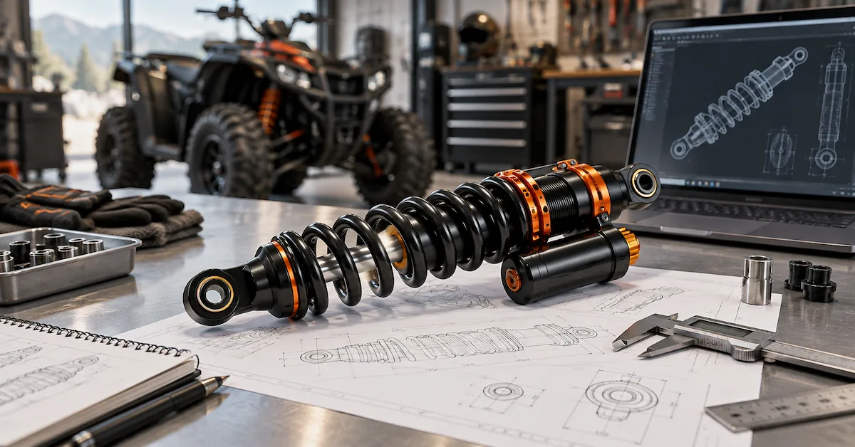
Start with a Dimension Checklist Organized by Function
Organize the drawing around installation, movement, and assembly requirements rather than adding dimensions wherever space is available. The following is a proposed buyer-side checklist, not a universal BEDO drawing standard or a list of fixed acceptance values. Include the features relevant to the selected mounting structure and shock architecture; identify unavailable information as pending engineering review. BEDO’s measurement guidance treats length, stroke, mounting details, and installation conditions as separate inputs.
| Dimension group | Information to include | Question it answers |
|---|---|---|
| Installation length | Extended and compressed dimensions using defined references | Does the shock match the required installation range? |
| Movement | Effective stroke and relevant stop conditions | What movement is available? |
| Upper mount | Mount type, hole or sleeve diameter, width, spacing, and orientation | Does the upper connection match the vehicle? |
| Lower mount | The corresponding lower-interface dimensions | Does the lower connection match the suspension? |
| Body and rod | Relevant outside diameters, lengths, and protruding features | Does the assembly fit its available space? |
| Spring and seats | Spring envelope, seat locations, installed reference condition, and adjustment range | Can the spring fit and operate without interference? |
| Reservoir and hose | Reservoir envelope, mounting position, fittings, and hose arrangement | Can the complete hydraulic assembly be installed? |
| Threads and hardware | Applicable thread callouts, engagement requirements, sleeves, spacers, and fastener interfaces | Can the assembly be connected as intended? |
| Tolerances and identification | Controlled limits, reference features, units, drawing number, and revision | Can manufacturing and inspection use the same definition? |
Define Extended and Compressed Length from the Same References
For an eye-to-eye shock, mounting-hole centers provide the installation reference; other mounting structures require appropriately defined centers, shoulders, or contact surfaces. Use the same references for extended and compressed dimensions, and show which configuration each value represents. A shock absorber technical drawing should not rely on one ambiguous “overall length” annotation. Where the design has adjustable installation length, state the approved range, reference setting, and relevant thread-engagement requirement. Also identify the compressed condition: first contact with a bump stop and the approved compressed limit should not be silently treated as identical. BEDO’s measurement guide emphasizes consistent references and cautions against forcing a gas-charged assembly closed with unsafe equipment. Have inaccessible compression measurements confirmed through an appropriate engineering procedure.
State Effective Stroke Instead of Asking Buyers to Calculate It
Record the required stroke explicitly and define whether it represents mechanical movement or the effective usable range. Subtracting extended and compressed installation dimensions gives nominal displacement only when the reference points and mechanical conditions are consistent. Stop arrangements and vehicle constraints still require review. Do not calculate compressed mounting length by subtracting catalog stroke from an undefined end-to-end dimension, and do not substitute wheel travel for damper stroke. BEDO’s length and stroke customization guide links dimensional changes with control-arm movement, bump-stop position, tire clearance, and suspension geometry. For a modified ATV, the drawing should describe the shock; the vehicle review must establish whether that movement is appropriate for the installation.
Detail Both Mounting Ends, Including the Hardware Arrangement
Treat the upper and lower connections as separate interfaces unless their complete specifications are genuinely identical. On your review copy, identify the hole or sleeve inside diameter, sleeve length, mounting width, bushing arrangement, and any spacers included in the assembly. For a clevis, show the inside spacing, leg geometry, hole location, and orientation; for a threaded stem, request the thread specification and relevant shoulder, engagement, and hardware dimensions. Add an end view or section where necessary to communicate the angular relationship between mounting features. A bolt passing through the hole does not establish complete mounting compatibility. BEDO’s ATV fitment guide specifically separates mounting widths, sleeves, bushings, spacers, and articulation from basic length checks.
Show the Maximum Body Envelope, Not Only the Main Tube Diameter
The installation envelope is the space occupied by the complete product. Record the relevant body diameter and length, then include protruding seal housings, collars, mounting eyes, adjusters, or other features that can approach surrounding components. Identify piston-rod diameter separately; an outside body diameter does not establish the internal bore or piston diameter. For a customer approval drawing, concentrate on the external dimensions needed for installation and inspection. Detailed internal manufacturing requirements can remain on linked component drawings where appropriate. BEDO’s CAD-based suspension development guide explains how surrounding vehicle geometry supports interference review. A clean side-view outline alone is insufficient when a wider collar or reservoir creates the actual clearance restriction.
Separate Spring Geometry from Spring Performance
For a complete coilover assembly, define or reference the spring’s free length, inside or outside diameter, relevant wire dimensions, end configuration, and seat interface. Show seat locations and the installed reference condition when they are needed to interpret assembly dimensions or preload adjustment. The drawing package should also identify the approved working range so engineering can evaluate spring seating and compression clearance. These geometric fields do not replace a spring-rate or load–deflection specification. BEDO’s custom coil spring guide treats dimensions, material properties, spring characteristics, and vehicle requirements as connected development inputs. In your shock absorber technical drawing, reference the approved spring specification rather than expecting color, coil count, or appearance to communicate performance.
Include Reservoir Position, Hose Interfaces, and Adjustment Access
For a piggyback design, show the reservoir’s dimensions and position relative to the body and mounting references. For a remote-reservoir design, also define the reservoir mounting arrangement, fitting orientation, and the agreed hose-length reference. Ask engineering to identify routing and bend requirements appropriate to the selected hose instead of adopting a universal value. Check the assembly through the relevant vehicle movement and include access to any controls that the customer is expected to use. BEDO’s remote-reservoir development guide discusses reservoir placement, hose routing, and clearance as development requirements. Although that guide addresses UTVs, an ATV project should apply the same review questions to its own installation—not inherit a UTV layout.
Define Tolerances Around the Interface, Not Just the Individual Part
A shock absorber technical drawing needs agreed limits on critical features, not nominal sizes alone. Review the mating vehicle bracket, sleeve or spacer stack, alignment, and intended clamping arrangement together. Consider a hypothetical rigid trial-fit example: a bracket opening of 32.2 ± 0.1 mm and an inserted mounting stack of 32.0 ± 0.2 mm produce a minimum opening of 32.1 mm and a maximum stack of 32.2 mm—a possible 0.1 mm interference despite the positive nominal gap. These are illustrative values, not BEDO specifications or recommended assembly clearances. The example shows why mating tolerances must be assessed together. Ask the responsible engineer to establish functional limits, reference features, the applicable drawing convention, and inspection methods; do not assign one tight tolerance to every visible dimension.
Two BEDO Models Show Why Catalog Dimensions Are Only a Starting Point
BEDO’s AU_HSA_02 and AU_HSA_04 both list an effective stroke of 80 mm, but their lengths, body diameters, and mounting interfaces differ. Both pages identify rear ATV/UTV applications and fixed damping. The comparison below preserves the published field names and provides preliminary screening data—not approved manufacturing dimensions, tolerances, or a vehicle-specific compatibility statement.
| Published specification | AU_HSA_02 | AU_HSA_04 |
|---|---|---|
| Installation position | Rear | Rear |
| Total length | 395 mm | 345 mm |
| Effective stroke | 80 mm | 80 mm |
| Cylinder outer diameter | 38 mm | 42 mm |
| Upper/lower mounting-hole diameter | 12 / 12 mm | 10 / 10 mm |
| Upper/lower mounting width | 40 / 32 mm | 32 / 30 mm |
| Adjustable damping levels | None | None |
The shared stroke does not establish interchangeability. Published total length differs by 50 mm, and both mounting-hole and width combinations are different. Neither page’s catalog table supplies a complete dimensioned drawing with all reference points and manufacturing tolerances. Before selecting either configuration for an OEM program, obtain the relevant shock absorber technical drawing and confirm the target vehicle interfaces. Do not derive a compressed eye-to-eye dimension from these catalog values without first establishing their definitions.
Link Dimensions to Materials, Manufacturing, and Performance Specifications
A dimensionally complete drawing can still leave important manufacturing requirements undefined. Reference approved material and finish specifications, assembly notes, and component records wherever the project requires them. Clarify whether critical dimensional limits apply to the finished assembly and how surface treatment is accounted for at interfaces. BEDO’s ATV shock absorber production guide connects engineering review, material selection, component manufacturing, assembly, and inspection. Keep compression and rebound requirements in a linked performance specification with defined test conditions rather than treating them as drawing dimensions. Likewise, an adjuster’s location is geometric information; its damping effect requires separate evaluation. A technically detailed drawing should point to those requirements without claiming to prove them.
Choose the Views That Make Inspection Unambiguous
For your drawing review, request an overall view, clear mounting-end details, and sections where hidden sleeves, bushings, shoulders, or contact surfaces cannot otherwise be understood. An additional end view can establish mounting-axis orientation or reservoir direction more clearly than an isometric picture. Avoid using a rendered image as the only source of dimensional information. When both 2D drawings and 3D CAD are provided, identify the approved relationship between them, including units, model configuration, and revision status. BEDO’s custom suspension development files guide recommends keeping drawings, models, measurements, and supporting records organized under revision control. If the files disagree, resolve the discrepancy before releasing the affected work rather than asking production to choose a value.
Verify the Drawing Through Prototype and Production Checks
Assign critical drawing features to an inspection record and agree the measurement method, assembly condition, and acceptance limit. Then keep three approvals distinct: the drawing is suitable for prototype manufacture; the prototype meets the agreed fitment and performance requirements; and production units reproduce the approved configuration. BEDO’s prototype-development guidance connects sample analysis, drawings, spring and damping development, testing, and production preparation. For installation-sensitive projects, dimensional inspection should be followed by appropriate vehicle-clearance and movement checks. Request current quality-system documents separately for supplier qualification, but do not treat a certificate as evidence that every dimension or performance requirement on your specific drawing has been verified.
Confirm the Drawing Scope Before Comparing Quotations
State whether the request covers a customer interface drawing, a complete assembly definition, internal component drawings, or a broader custom-development program. Ask suppliers to separate drawing preparation, sample measurement, CAD work, engineering review, prototypes, testing, and recurring product cost. For OEM or private-label orders, keep logos and packaging linked to the technical version without using artwork approval as production authorization. BEDO’s low-volume OEM guide describes prototype and small-batch support; exact quantities, available production allocation, and timing still require project confirmation. Request stage-specific milestones and clarify whether revisions and final editable files are included. Agree the ownership and permitted use of supplied and newly created documents before transferring confidential information.
Frequently Asked Questions
Is Overall Length Enough for a Shock Absorber Drawing?
No. Length must have defined references, and the drawing also needs the relevant mounting, stroke, envelope, and tolerance information. An assembly can match one nominal length while differing at the interfaces that determine installation.
Should Extended and Compressed Dimensions Use the Same Reference Points?
Yes. Use consistent mounting centers or other explicitly defined installation references. Otherwise, subtracting the values does not establish meaningful damper displacement. For non-eye mounting structures, show exactly which surfaces or axes define the dimensions.
Should Stroke Be Listed Separately?
Yes. State the required movement explicitly and define its limits. Keep mechanical displacement, effective usable stroke, and vehicle wheel travel distinguishable; they should not be combined into one undefined “travel” field.
Do Upper and Lower Mounts Need Separate Details?
Record them separately unless the complete interfaces are identical. Check widths, sleeves, bushings, spacers, and orientation as well as hole diameter. A shared bolt size does not establish that both ends use the same mounting arrangement.
What Tolerances Should I Put on the Drawing?
Ask engineering to derive limits from fit, function, mating components, manufacturing capability, and inspection requirements. Do not copy tolerances from an unrelated model or select uniformly tight limits merely to make the drawing appear more precise.
Should Spring Rate Be Included?
Include it directly or reference the approved spring specification, but distinguish it from geometric dimensions. Spring rate needs complete units and an application-based requirement; spring envelope dimensions alone do not define the required load response.
Must Every Internal Component Appear on the Customer Drawing?
Define the deliverable with the supplier. A customer fitment document can focus on external interfaces, while a complete manufacturing package may require linked component drawings and specifications. Do not mistake an interface approval for approval of undocumented internal details.
Can a Drawing Be Created from an Existing Sample?
BEDO describes sample analysis and drawing review within its development support. Provide the sample’s application and condition, identify wear or modifications, and distinguish measured reference information from requirements that must be retained in the new design.
Do I Need Full Vehicle CAD?
Ask which geometry is necessary for the task. Relevant mounts and surrounding components may be enough for an installation review; a shock model alone cannot establish clearance from vehicle parts that are absent from the supplied data.
What Should Prevent a Drawing from Being Released?
Keep the affected work pending when critical dimensions lack references, mating interfaces are unresolved, models and drawings conflict, or acceptance requirements remain undefined. Record open items and the responsible decision-maker instead of treating missing information as implied approval.
Conclusion
A useful shock absorber technical drawing defines what must fit, how movement is measured, which features require dimensional control, and how the finished assembly will be inspected. Prioritize extended and compressed references, effective stroke, both mounting interfaces, body and spring envelopes, reservoir arrangements, and functional tolerances. Link those dimensions to the approved materials, performance requirements, and document revisions before releasing prototypes or production. BEDO manufactures shock absorbers and springs and provides customization and design support through its manufacturing services. To begin a drawing review, send BEDO your existing drawing, CAD, or reference-sample information, together with vehicle details, known dimensions, required changes, and expected quantities. Request confirmation of unresolved dimensions and the approval scope before manufacturing starts.