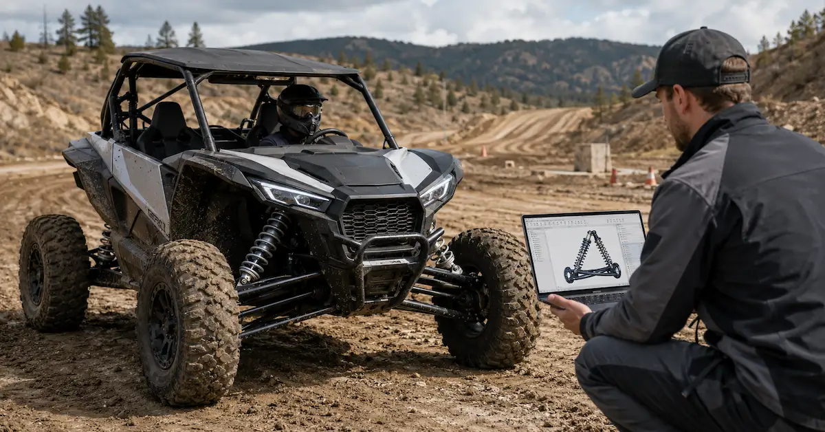
For a new OEM project, combining vehicle information with CAD, drawings, and prototype testing generally gives engineers a stronger basis for development than relying on any single source.
When Is CAD-Based Suspension Development Most Valuable?
New Vehicle Platforms
New vehicles may not have an existing production suspension available for direct reference.
CAD provides a structured starting point for developing the installation geometry.
Electric Vehicles
Battery packaging and vehicle weight distribution can create different suspension and packaging requirements compared with an existing combustion-powered platform.
The exact effect depends on the vehicle architecture, so it should be evaluated project by project rather than assumed.
ATV and UTV Development
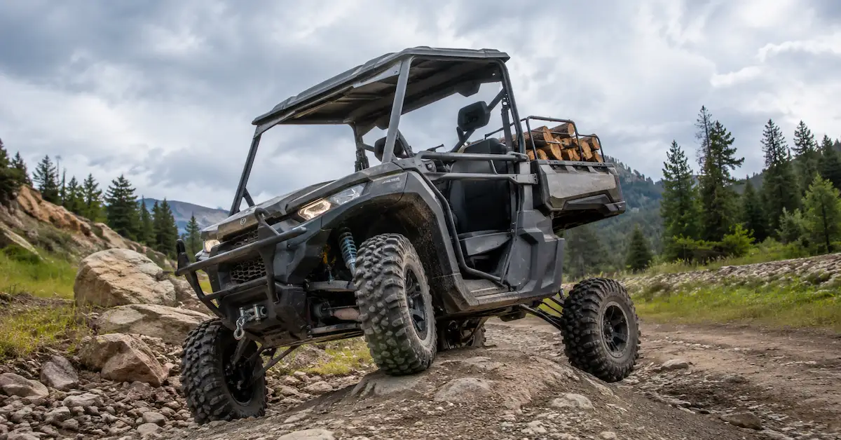
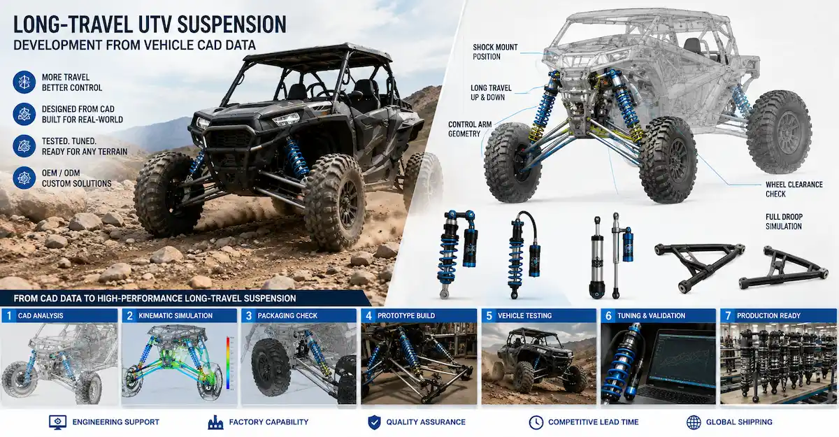
Off-road suspension needs sufficient room for wheel movement and must operate around chassis, control-arm, tire, and drivetrain packaging.
Bedo supports suspension engineering and prototype development for ATV and UTV applications.
Specialty Vehicles
Utility, agricultural, low-volume, and specialty platforms frequently use non-standard installation dimensions.
In such projects, CAD-based development can help define a custom solution before committing to a larger manufacturing program.
What Should Buyers Check Before Approving a CAD Suspension Design?
Do not approve a suspension model only because the rendering looks complete.
Use an engineering checklist.
Geometry
Confirm:
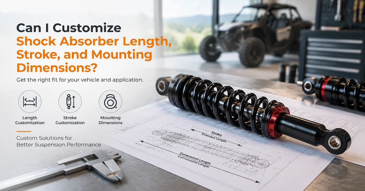
Extended length
Compressed length
Stroke
Mount-center definitions
Mounting-hole dimensions
Spring clearance
Body clearance
Reservoir clearance
Vehicle Interfaces
Confirm:
Chassis mount
Suspension-arm mount
Bolt and bushing dimensions
Nearby-component clearance
Engineering Status
Ask:
Which dimensions are confirmed?
Which parameters are estimates?
Which parameters require prototype validation?
Has the drawing revision been recorded?
Does this model represent concept, prototype, or production status?
Performance Requirements
Confirm separately:
Target spring rate
Preload
Compression behavior
Rebound behavior
Intended terrain
Vehicle load range
CAD should not create false confidence around performance data that has not yet been tested.
How to Choose a CAD Suspension Development Partner
A CAD operator and a suspension-development partner are not necessarily the same thing.
For OEM projects, buyers should evaluate whether the supplier can connect digital design with physical suspension engineering.
Look for capability in:
Vehicle requirement analysis
CAD and drawing review
Sample analysis
Shock absorber development
Spring matching
Damping optimization
Prototype manufacturing
Performance testing
Engineering revisions
Small-batch production
OEM manufacturing
A supplier capable of supporting these stages can maintain continuity from digital concept through physical validation.
Bedo currently presents its engineering service as a combination of customized shock absorber engineering, prototype development, testing validation, and OEM manufacturing for ATV, UTV, motorcycles, golf carts, utility vehicles, electric vehicles, and specialty vehicles.
How Bedo Auto Supports CAD-Based Suspension Development
Bedo Auto's published development workflow includes:
Sample analysis
Technical drawing review
Suspension design support
Prototype manufacturing
Spring development
Shock absorber tuning
Performance testing
Small-batch validation
OEM manufacturing
This makes CAD review part of a wider prototype-to-production process, rather than an isolated drafting service.
Buyers can begin with:
A physical shock absorber
Existing drawings
CAD files
Vehicle specifications
Technical requirements
and then move toward prototype development and validation.
You can review Bedo's related Suspension Sample Development content for the next stage from digital definition into physical sample development. Bedo describes this process as supporting OEM suspension projects from initial samples to production solutions.
For projects requiring smaller initial quantities after prototype validation, see the Low Volume Shock Absorber OEM Guide. Bedo currently lists customization, prototype production, damping optimization, small-batch manufacturing, performance testing, and OEM production support within that workflow.
What Should You Send for a CAD Suspension Development RFQ?
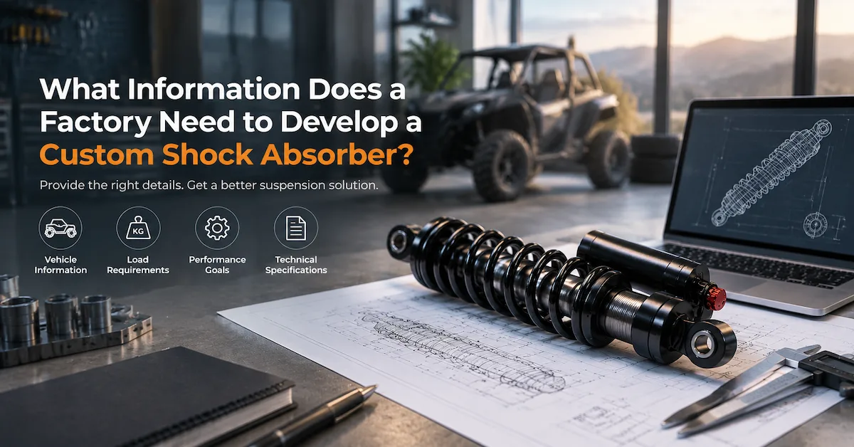
Before requesting a quotation or engineering review, prepare as much information as possible:
Vehicle type and application
Front or rear suspension position
Vehicle empty weight
Maximum loaded weight
Available suspension travel
Existing shock dimensions
Upper and lower mounting details
Vehicle CAD files if available
Existing 2D drawings
Reference shock absorber
Installation photographs
Spring information if available
Performance target
Terrain and operating environment
Prototype quantity
Expected future production plan
If you do not have all these items, provide the available information and identify what still needs engineering confirmation.
For project review, buyers can submit drawings, samples, and technical requirements through the Bedo Auto contact page.
FAQ
What is CAD-based suspension development?
CAD-based suspension development uses digital models and technical drawings to define suspension geometry, mounting interfaces, installation space, and component configuration before prototype manufacturing.
Can CAD determine the correct shock absorber size?
CAD can help define available space, mounting locations, compressed and extended lengths, and stroke requirements. Final suitability should still be verified using the actual suspension geometry and prototype testing.
Can a suspension design be created from vehicle CAD?
Yes. Vehicle CAD can provide valuable information about mounting locations, surrounding structures, packaging space, and possible interference. Additional vehicle and performance specifications are still required.
Can you create CAD from an existing shock absorber sample?
A physical shock can provide dimensions and structural reference data for CAD development. If the new vehicle application differs from the original one, the design should be reviewed rather than copied automatically.
Does CAD determine spring rate?
No. CAD can define spring packaging and geometry, but spring rate selection depends on factors such as vehicle load, suspension geometry, intended travel, ride-height target, and application.
Can CAD calculate compression and rebound damping?
CAD geometry alone does not validate real damping characteristics. Compression and rebound behavior need separate engineering definition and physical testing.
Do OEM projects need both 2D and 3D drawings?
Not always. 3D models are especially useful for packaging and geometry review, while 2D drawings are useful for dimensions, tolerances, manufacturing notes, and approval control. ISO 16792:2021 supports both 3D-only and combined 3D/2D digital product-definition approaches.
What happens after CAD suspension design is completed?
For a new custom suspension project, the next stages normally involve prototype manufacturing, installation verification, testing, engineering revision, and eventual production preparation.
Can CAD designs be revised after prototype testing?
Yes. Prototype results may require adjustments to geometry, mounting, stroke, spring configuration, reservoir arrangement, or other design features. Revision is a normal part of engineering development.
How can I start a CAD-based suspension project with Bedo Auto?
Prepare available CAD files, drawings, vehicle specifications, reference shock absorbers, installation information, load data, and performance requirements, then submit the project through Bedo Auto for technical review. Bedo's current published workflow accepts drawings, CAD files, physical samples, vehicle specifications, and technical parameters as development inputs.
Conclusion
CAD-based suspension development gives OEM vehicle manufacturers a structured way to define suspension geometry and identify fitment or packaging problems before physical prototypes are produced.
Its greatest value is not simply creating a 3D model. A useful CAD process connects vehicle requirements, shock absorber geometry, mounting interfaces, installation space, technical drawings, prototype production, physical testing, and engineering revisions.
Digital product-definition standards such as ISO 16792:2021 provide established practices for preparing and presenting 3D and combined 3D/2D engineering data, but digital models still cannot replace suspension performance validation.
For ATV, UTV, motorcycles, electric vehicles, utility vehicles, golf carts, and specialty vehicles, Bedo Auto combines technical drawing review and suspension design support with prototype manufacturing, spring development, shock tuning, performance testing, small-batch validation, and OEM manufacturing.
If your project begins with a vehicle CAD model, existing suspension drawing, reference shock, or new vehicle requirement, submit the available engineering information through the Bedo Auto contact page for a project-specific review.