
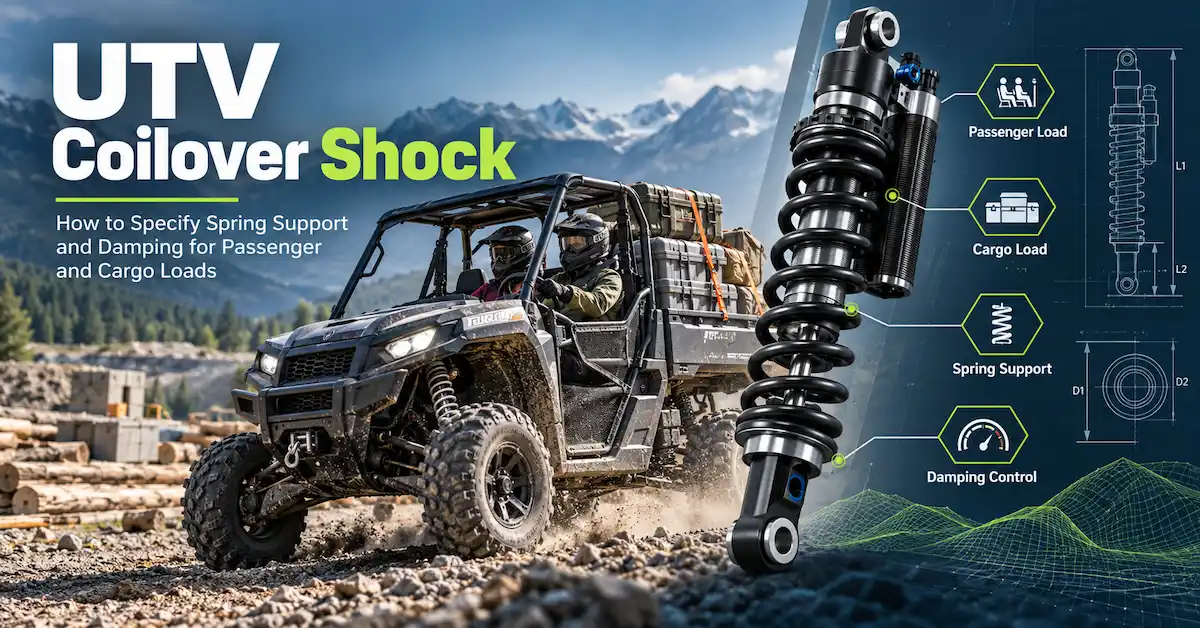
How should buyers specify a UTV coilover shock?
Direct answer: specify a UTV coilover shock as a matched spring-and-damper assembly for defined vehicle load states. The RFQ should state front or rear position, extended and compressed length, shock stroke, wheel travel and motion ratio, mounting interfaces, curb axle load, passengers, cargo, accessories, spring rate and preload target, compression and rebound control, terrain, speed, environment, and validation method.
A useful coilover is not simply a shock with a spring around it. Spring support determines ride height and reserve travel; damping controls how that spring-and-vehicle mass moves. Both must work across the empty, normal, and maximum routine conditions without creating interference, coil bind, bottoming, excessive rebound, or an impractical customer setup.
This article is written for UTV OEMs, utility-vehicle brands, aftermarket companies, fleet suppliers, agricultural and resort vehicle developers, distributors, and private-label buyers. Its unique task is to convert passenger and cargo variation into a coilover specification and validation plan. It does not repeat a general UTV load guide, a fixed-versus-adjustable article, or a supplier-ranking page.
What is a UTV coilover shock?
A coilover combines a coil spring and shock absorber around a common assembly. The spring supports the sprung mass and stores energy as the suspension compresses. The damper converts suspension motion into controlled resistance in compression and rebound. A spring seat, preload adjuster, body, rod, seals, mounting eyes, bushings, and sometimes a gas chamber or reservoir complete the assembly.
This arrangement packages spring support and motion control in one location, but it also connects their specifications. Changing spring rate or preload changes the force the damper must control. Changing installed length or mounting angle changes ride height and motion ratio. Changing damping cannot correct an unsafe fit or a spring that is outside its load range.
| Coilover element | Primary role | Buyer specification |
|---|---|---|
| Coil spring | Supports UTV and payload; establishes working ride-height range. | Rate, free/installed length, geometry, material/finish, preload and tolerance. |
| Shock body and rod | Guide motion and contain damping system. | Length, stroke, diameters, material/finish, seal interface and clearance. |
| Compression valving | Controls resistance as suspension compresses. | Force/curve under stated speed, setting, temperature and tolerance. |
| Rebound valving | Controls return after the spring releases energy. | Force/curve under the same defined test framework. |
| Preload mechanism | Adjusts initial spring compression and setup height. | Adjustment range, baseline, locking, access and customer instruction. |
| Mounting interfaces | Transfer force into chassis and suspension arm/linkage. | Hole, sleeve, width, bushing, articulation, orientation and fastener. |
Build UTV load cases before selecting a spring
A UTV can operate as an empty transport vehicle, two-person recreational vehicle, multi-passenger shuttle, farm utility machine, cargo carrier, tow vehicle, or accessory platform. The same vehicle may move between several states in one day. Define the routine states rather than giving the supplier only the maximum payload shown in a brochure.
State A: curb or maintenance condition
Record vehicle mass, fuel or battery state, tools permanently carried, and front/rear axle loads. This state matters because an over-stiff spring or too much damping can make the empty vehicle harsh and reduce tire contact.
State B: normal operating condition
Record typical driver, passengers, cargo, and accessories. This should be the primary calibration condition for many fleet or utility programs because it represents most operating hours.
State C: maximum routine condition
Record the highest load expected regularly, its location, and any trailer tongue load. "Routine" is important: an emergency or transport limit should not necessarily determine everyday ride quality. Confirm the vehicle-level structural and legal limits separately; a coilover change does not increase the approved vehicle payload by itself.
State D: special accessory condition
Snow equipment, sprayers, racks, cab enclosures, batteries, winches, tool boxes, and rear seats can concentrate mass at one axle. Record whether the accessory is permanent, seasonal, or optional. If the variation is large, one fixed spring-and-damper setup may require a compromise or separate part numbers.
| Load-state record | Minimum data | Why it changes the coilover decision |
|---|---|---|
| Front/rear axle load | Measured value for each operating state. | Shows the actual load carried by each suspension end. |
| Passengers | Number, assumed mass and seating position. | Changes side and axle load, ride height, pitch and comfort. |
| Cargo | Mass, center/location and frequency. | Determines rear support and reserve travel. |
| Accessories | Mass, location and permanent/optional status. | Can create a new calibration or separate SKU. |
| Towing | Tongue load and attachment geometry, not only trailer mass. | Creates sustained rear load and pitch effects. |
| Duty cycle | Hours, surfaces, speed, obstacles and load-state percentage. | Determines which state should dominate tuning and durability work. |
Choose spring rate, preload, and installed length together
Spring rate is the load change per unit deflection under a defined convention. It should be chosen with axle load, number of coilovers per axle, motion ratio, installation angle, desired ride height, sag, and available stroke. A published "LBS" value without the complete measurement and tolerance should be confirmed before release.
Spring rate defines load response
A softer spring compresses more for a given load and may improve light-load compliance, but can use too much travel with passengers or cargo. A stiffer spring preserves ride height under load but can be harsh when empty. The correct choice balances the operating distribution, not just the maximum condition.
Preload establishes the starting point
Preload can set the initial working position within the spring and geometry limits. It does not change the spring's basic rate. Excess preload can reduce extension reserve, make setup difficult, or hide an unsuitable spring. Record the baseline in turns, millimeters, or an unambiguous seat dimension and lock it for production.
Installed length affects force and clearance
Document free spring length, installed length at full droop or assembly condition, normal ride position, and maximum compression. Check coil bind, seat contact, adjuster thread engagement, and spring-to-body clearance. If a tender or dual-rate arrangement is proposed, also define crossover behavior and component identity.
Sag is a validation result, not the only target
Measure sag at repeatable chassis points for curb, normal, and maximum routine load. Ensure adequate bump and droop travel remain. An acceptable static number does not prove control over repeated bumps, cornering, braking, or heat, so combine it with dynamic testing.
Match damping to the spring and duty cycle
A UTV coilover shock needs enough compression control to manage impacts and load transfer without becoming harsh, and enough rebound control to manage spring return without packing over repeated bumps. The desired force depends on spring, motion ratio, mass, speed, tire, temperature, and terrain.
Low-speed and high-speed shock motion
Shock-shaft speed is not the same as vehicle speed. Body roll, pitch, gradual load transfer, and some terrain events can create lower shaft speeds, while sharp obstacles can create faster movement. If a supplier offers curve data, examine the relevant range rather than comparing one maximum number.
Heat and repeated use
Long utility routes, washboard surfaces, or repeated off-road impacts can change oil temperature and damping behavior. Define the real work cycle and inspect performance before and after the representative run. Do not claim fade resistance or a temperature limit without a documented condition and result.
Fixed or adjustable setup
A fixed setting can be effective for a controlled fleet configuration. Adjustment is useful when the operator has distinct load or terrain modes and a clear map. Adjustment also adds cost, inspection, labeling, misuse risk, and after-sales questions. Choose it only when it solves a documented condition.
Geometry and packaging decide whether the coilover can work
Measure extended length, compressed length, stroke, upper/lower hole, mounting width, sleeve and bushing, body and spring diameters, installation angle, and reservoir envelope. If the UTV uses a linkage, supply pivot locations or a motion-ratio model. Validate through full bump and droop with final tires, wheels, drive shafts, brakes, body, cargo bed, and accessories.
A coilover must not reach coil bind or internal bottom before the intended bump stop. It must not unseat the spring at droop. The reservoir or body must not contact the chassis, and the adjuster must remain accessible. Mounting brackets must accommodate articulation without side-loading the shock.
When replacing an existing part, measure the sample but also inspect the vehicle. A worn bushing, bent bracket, sagged spring, or modified mount can make the sample a poor design authority. Record what should be copied and what should be corrected.
Public BEDO references for a UTV coilover discussion
BEDO's AU_HSA_02 public page lists a rear ATV/UTV shock with an internal gas chamber and oil-gas separation, aluminum alloy and steel pipe, 395 mm total length, 80 mm effective stroke, 250 LBS spring rate, 3000 N rebound, 550 N compression, 3.8 kg weight, 12 mm upper/lower holes, 40 mm upper width, 32 mm lower width, and fixed damping. The page states a 0.1 m/s inspection speed.
AU_HSA_04 is listed as a rear beach ATV/UTV reference with the same general material description and damping architecture, 345 mm total length, 80 mm effective stroke, 225 LBS spring rate, 3000 N rebound, 350 N compression, 3.2 kg weight, 10 mm holes, 32 mm upper width, 30 mm lower width, and fixed damping. It also states a 0.1 m/s inspection speed.
| Selection field | AU_HSA_02 public value | AU_HSA_04 public value |
|---|---|---|
| Total length / stroke | 395 mm / 80 mm | 345 mm / 80 mm |
| Cylinder outer diameter | 38 mm | 42 mm |
| Listed spring rate | 250 LBS | 225 LBS |
| Listed rebound / compression | 3000 N / 550 N | 3000 N / 350 N |
| Mounting holes | 12 mm upper and lower | 10 mm upper and lower |
| Mounting widths | 40 mm upper / 32 mm lower | 32 mm upper / 30 mm lower |
| Adjustability | None listed | None listed |
The table shows why identical effective stroke does not make two assemblies interchangeable. Length, body diameter, spring, compression force, mounting holes, and widths differ. The buyer must match the complete interface and UTV load profile.
Build a coilover prototype plan
Gate 1: vehicle and load approval
Freeze platform revision, front/rear position, axle loads, passengers, cargo, accessories, tire, wheel, speed, terrain, environment, and target. Mark estimated data. Confirm that the coilover project does not imply a higher legal or structural payload rating.
Gate 2: interface review
Approve extended/compressed length, stroke, mounting, spring and body envelope, motion ratio, bump/droop limits, coil-bind clearance, and adjuster or reservoir access. Review CAD and a physical vehicle where possible.
Gate 3: sample configuration
Give each sample a revision. Record spring identity, rate, free and installed length, preload, damping setting, force evidence, gas/reservoir configuration, mounting hardware, finish, and label. Photograph it before installation.
Keep a tuning matrix instead of relying on driver memory
For each prototype, give the spring, preload position, damping configuration, shock revision, and vehicle setup a unique identifier. Use a simple matrix to compare curb, normal, and loaded states on the same route. Record ride height, sag, available compression and droop, bottoming events, repeated-impact recovery, steering response, passenger comments, cargo movement, leakage, temperature observations, and post-test inspection. Note tire pressure, driver, speed range, weather, and accessory configuration because they can change the result.
Change one controlled variable at a time where practical. If the team changes the spring, preload, and damping together, it may find a better setup but will not know why it improved or how to reproduce it. Preserve the previous known configuration and document every adjustment in measurable turns, clicks, dimensions, or part numbers rather than "softer" and "harder."
The final tuning record should identify the approved load envelope and its limits. If one UTV coilover shock setup is acceptable for normal passengers but not for a maximum accessory package, state that boundary and define the alternate configuration or operating restriction. This makes the engineering conclusion usable by purchasing, production, service teams, and future model revisions.
Gate 4: static vehicle checks
Measure ride height and sag at curb, normal, and maximum routine loads. Check spring seating, clearance, bump and droop reserve, fastener alignment, and left/right consistency. Do not begin dynamic work if there is interference or uncertain mechanical travel.
Gate 5: dynamic validation
Use representative surfaces and loads. Evaluate small-bump compliance, larger impacts, repeated bumps, braking, acceleration, turns, slopes, cargo stability, passenger comfort, bottoming, top-out, rebound, noise, leakage, and temperature-related change. Keep tire pressure and other vehicle variables controlled.
Gate 6: pilot and release
Compare pilot units for dimensions, spring data, preload, damping evidence, leakage, adjustment where applicable, finish, labels, and packaging. Freeze the drawing, BOM, test limits, inspection plan, part number, revision, and change-notification rules before repeat production.
Quality records should connect to the released part
| Record | Useful content | Traceability link |
|---|---|---|
| Dimensional report | Length, stroke, holes, widths, body, spring and reservoir envelope. | Part number, drawing revision and measured unit. |
| Spring record | Rate or load points, free length, dimensions, finish and identification. | Spring lot and coilover assembly batch. |
| Damping record | Compression/rebound under defined speed, setting, temperature and limits. | Shock serial/sample or production batch. |
| Functional check | Leakage, rod movement, noise, adjuster action and assembly condition. | Inspection date, operator and lot. |
| Vehicle validation | Configuration, loads, route, measurements, observations and approval. | Sample revision and vehicle revision. |
| Packaging approval | Protection, hardware, label, barcode, instructions and carton. | Released SKU and packaging revision. |
Generic certificates or factory photographs can support supplier qualification, but they do not prove that the shipped coilover matches the approved vehicle configuration. Evidence becomes actionable when it is connected to a part, revision, batch, and test condition.
Define the commercial path before ordering samples
Request separate commercial terms for engineering review, prototypes, revisions, pilot batch, first production, and repeat orders. Ask which tooling, fixtures, test work, custom spring, colors, labels, or cartons are included. A low sample price can exclude the engineering evidence needed for release.
BEDO's company page states support for small-batch ordering but does not publish one universal MOQ. Confirm minimum quantities for the exact UTV coilover shock, spring variation, branding, and packaging. Also confirm lead time by stage and when the clock starts: receipt of sample, drawing approval, deposit, material approval, or final artwork.
Packaging should prevent spring and body finish damage, protect mounting eyes and adjusters, contain hardware, identify front/rear or left/right where needed, and connect the carton to the released vehicle application. For a multi-SKU aftermarket program, packaging errors can create as many returns as technical defects.
Prepare a UTV coilover shock RFQ
Provide UTV brand or project code, model year, position, number of coilovers, suspension layout, axle loads at all operating states, passenger and cargo locations, accessories, towing condition, tire, wheel, ride height, geometry, extended/compressed length, stroke, mounting interfaces, spring and damper sample data, terrain, speed, duty cycle, environment, current complaint, and target result.
Add sample quantity, pilot quantity, annual volume, color, logo, label, instruction, hardware, packaging, delivery destination, and launch date. If information is unknown, mark it for joint confirmation. Do not enter a guessed spring rate or damping force just to complete the form.
Ask BEDO to return the recommended reference or development path, assumptions, missing information, proposed spring/preload/damping configuration, sample revision, test plan, MOQ by stage, lead time by stage, price basis, packaging, evidence supplied, and change-control process. Buyers can also review the shock absorber category before sending the project package.
UTV coilover shock FAQ
Is a coilover the spring, the shock, or both?
It is an assembly in which the coil spring is packaged around the damper. The spring supports load; the damper controls compression and rebound motion.
Can one UTV coilover shock cover empty and fully loaded use?
Sometimes, if the load range and performance compromise are acceptable. Large variations may require adjustment, a different spring, or separate SKUs. Validate all routine states.
Does preload increase spring rate?
For a conventional linear spring, preload changes initial compression and setup position, not the basic rate. It cannot correct every load mismatch.
Why does motion ratio matter?
Wheel movement and force are translated through suspension geometry into shock movement and force. The same coilover can behave differently at another mounting point or angle.
Are AU_HSA_02 and AU_HSA_04 interchangeable?
No such claim should be made. Their published length, body diameter, spring, compression value, holes, and widths differ. Each requires application review.
When should adjustable damping be used?
Use it when distinct load or terrain conditions require a documented setting change and the operator can access and understand the control. Otherwise, a validated fixed setup may be simpler.
What must be tested with cargo?
Check ride height, sag, remaining travel, bottoming, rebound, cornering, braking, slopes, cargo stability, heat, noise, leakage, and passenger comfort on representative surfaces.
Does a stronger coilover increase UTV payload capacity?
No. Suspension changes do not by themselves raise chassis, brake, tire, axle, legal, or manufacturer payload ratings. The complete vehicle must be approved.
What must BEDO confirm before publication?
Confirm the product values, current revisions, author and engineer, applicable process/test records, project MOQ, stage lead times, packaging, and any customer case. Do not infer these from general website language.
Conclusion
A UTV coilover shock must be specified as a spring-and-damper system for defined vehicle loads. Axle measurements, motion ratio, ride height, stroke, mounting, spring rate, preload, compression, rebound, terrain, and duty cycle belong in one requirement. Prototype gates and traceable quality records then connect vehicle performance to repeat production.
BEDO Auto's AU_HSA_02 and AU_HSA_04 pages provide concrete reference data for two rear ATV/UTV assemblies, including different lengths, spring rates, damping values, body sizes, and mounting dimensions. Those differences are the reason to send a full UTV RFQ rather than request a generic coilover. BEDO can then confirm whether an existing reference or a project-specific configuration is appropriate.